Ford Parts Wiki | GM Parts Wiki
Home | Search | Browse
Prev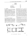
 Next
Next
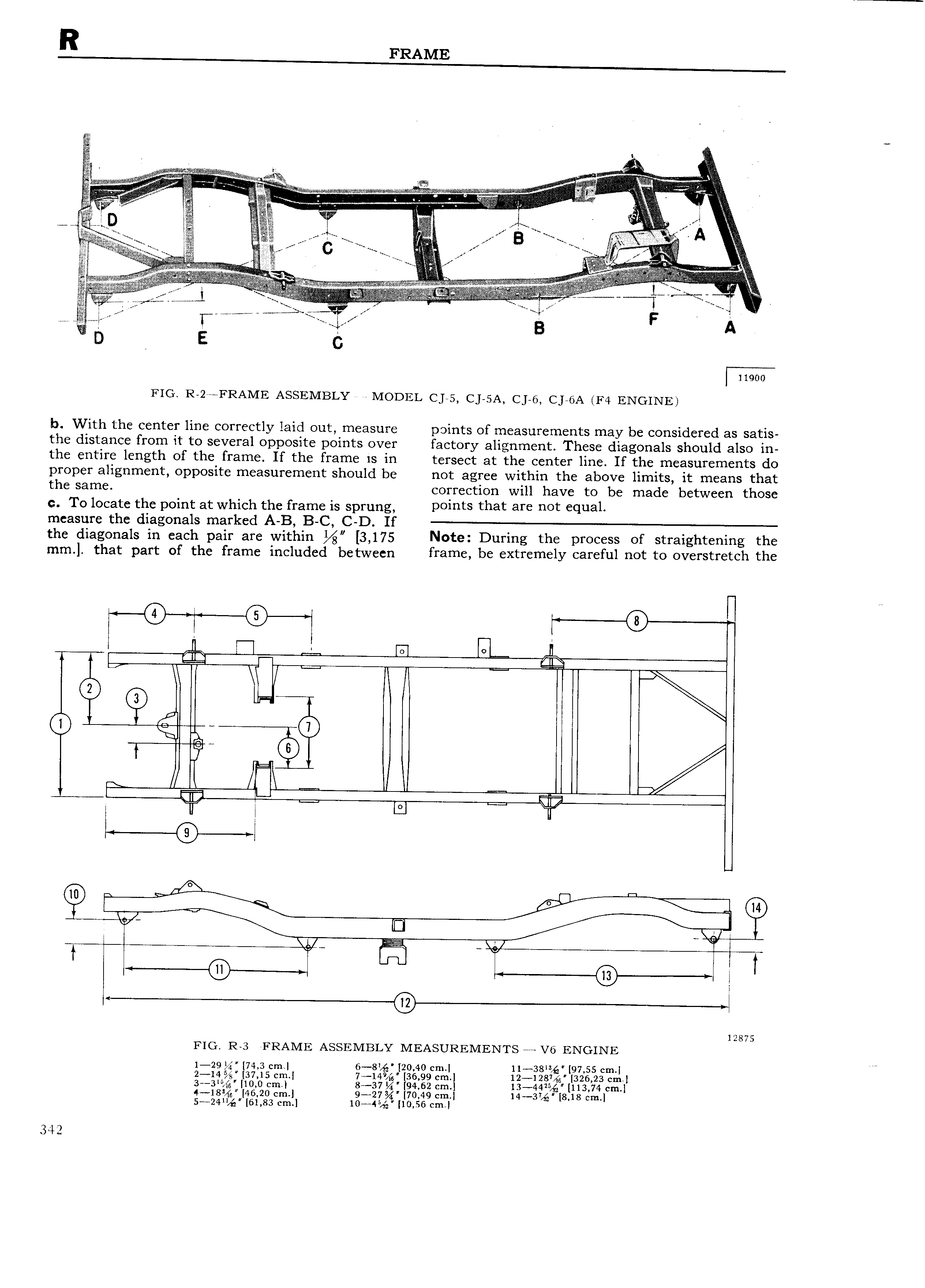
1 v v z ii t I i J gyzittv W tr B s A 1 i it E gi isle gr C 1 s V ig z VVAV gig zi L J f Q t W vA j r 4 B A D E 5 11900 FIG R 2 FRAME ASSEMBLY MODEL cys c HA c ye c Jaap E4 ENGINE b With the center line correctly laid out measure points of measurements may be considered as satis the distance from it to several opposite points over factory alignment These diagonals should also in the entire length of the frame If the frame is in tersect at the center line If the measurements do proper alignment opposite measurement should be not agree within the above limits it means that the same correction will have to be made between those c To locate the point at which the frame is sprung P01 t that aff 0t l 81 measure the diagonals marked A B B C C D If the diagonals in each pair are within 3 175 Note During the process of straightening the mm that part of the frame included between frame be extremely careful not to overstretch the 0 6 R aa Q1 0 c H1 ml E e 2 A 0 L 49 ms Q f l Y T 6 1 l 12875 FIG Re FRAME ASSEMBLY MEAsuREMENrs at ve ENGINE 1 29 74 3 cm 6 8 20 40 cm 11 38 97 55 cm 2 14 37 15 cm 7 14 36 99 cm 12 1287 g1 326 23 cm 3 3 10 0 cm 8 37 Bi 94 62 cm 13 44Z 113 74 cm 4 18 Q 46 20 cm 9 27 70 49 cm 14 37 8 18 cm 5 24 B 61 83 cm 10 45 Z 10 56 cm 342