Ford Parts Wiki | GM Parts Wiki
Home | Search | Browse | Marketplace | Messages | FAQ | Guest
|
Technical Service Manual January 1975 |
|
Prev
 Next
Next
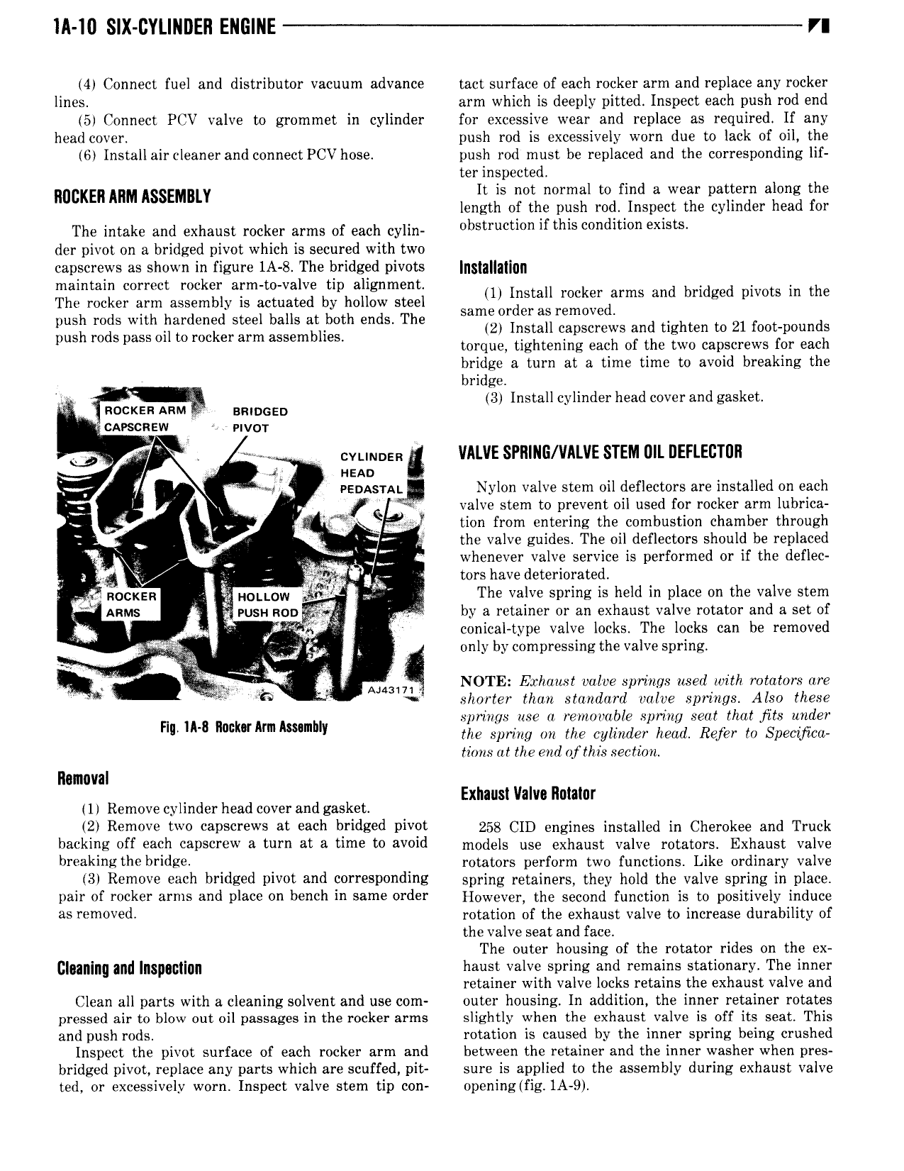
lA l0 SIX CYLINDER ENGINE VI 4 Connect fuel and distributor vacuum advance tact surface of each rocker arm and replace any rocker lines arm which is deeply pitted Inspect each push rod end 5I Connect PCV valve to grommet in cylinder for excessive wear and replace as required If any head cover push rod is excessively worn due to lack of oil the 6 Install air cleaner and connect PCV hose push rod must be replaced and the corresponding lif ter inspected It is not normal to find a wear pattern along the VVVKEV Mm ASSEMBLY length of the push rod Inspect the cylinder head for The intake and exhaust rocker arms of each cylin bslr lf mls dm SlS der pivot on a bridged pivot which is secured with two capscrews as shown in figure 1A 8 The bridged pivots 3 iq maintain correct rocker arm to valve tip alignment The rocker arm assembly is actuated by hollow steel ll llllllllll locker llllllls allll lllllllgglll plwlls lll the push rods with hardened steel balls at both ends The S l S l h 21 f d push rods pass oil to rocker arm assemblies l2l lllslall llallscllells and llg tell lo lllll pollll S torque tightening each of the two capscrews for each bridge a turn at a time time to avoid breaking the bridge I 3 Install cylinder head cover and gasket aocxzn Aim gmpggp carscazw r rivor L ovtmnzn E VALVE SPNING VALVE STEM DIL IIEFLEDTIIN J rteA lr i PEDASTA 5 Nylon valve stem oil deflectors are installed on each Q fl Q valve stem to prevent oil used for rocker arm lubrica if tion from entering the combustion chamber through T X the valve guides The oil deflectors should be replaced e e 4 whenever valve service is performed or if the deflec i V L ji I v e tors have deteriorated l ha Rqcxgn w r l J The valve spring is held in place on the valve stem Tl ARMS l PUSH ROD by a retainer or an exhaust valve rotator and a set of v I T l conical type valve locks The locks can be removed T only by compressing the valve spring ri r i w Mum NOTE Exhaust valve springs used with rotators are M R shorter than standard valve springs Also these springs use a removable spring seat that fits under Flu lA ll llllllllllllllll Awllllllll the spring on the cylinder head Refer to Specifica tions at the end of this section llamuval A Exhaust Valve llnlalur ll Remove cylinder head cover and gasket Zi Remove two capscrews at each bridged pivot 258 CID engines installed in Cherokee and Truck hacking Off Bach DS W 3 Wm at 9 time W avoid models use exhaust valve rotators Exhaust valve b1 1l i H h bY ldH rotators perform two functions Like ordinary valve Sl Remove each bridged pivot and corresponding spring retainers they hold the valve spring in place noir of rocker arms and place on bench in Same order However the second function is to positively induce 85 removed rotation of the exhaust valve to increase durability of the valve seat and face The outer housing of the rotator rides on the ex clganlng and lngpggliim haust valve spring and remains stationary The inner retainer with valve locks retains the exhaust valve and Clean all parts with a cleaning solvent and use com outer housing In addition the inner retainer rotates pressed air to blow out oil passages in the rocker arms slightly when the exhaust valve is off its seat This and push rods rotation is caused by the inner spring being crushed Inspect the pivot surface of each rocker arm and between the retainer and the inner washer when pres bridged pivot replace any parts which are scuffed pit sure is applied to the assembly during exhaust valve ted or excessively worn Inspect valve stem tip con openingifig 1A 9