Ford Parts Wiki | GM Parts Wiki
Home | Search | Browse | Marketplace | Messages | FAQ | Guest
|
Technical Service Manual January 1975 |
|
Prev
 Next
Next
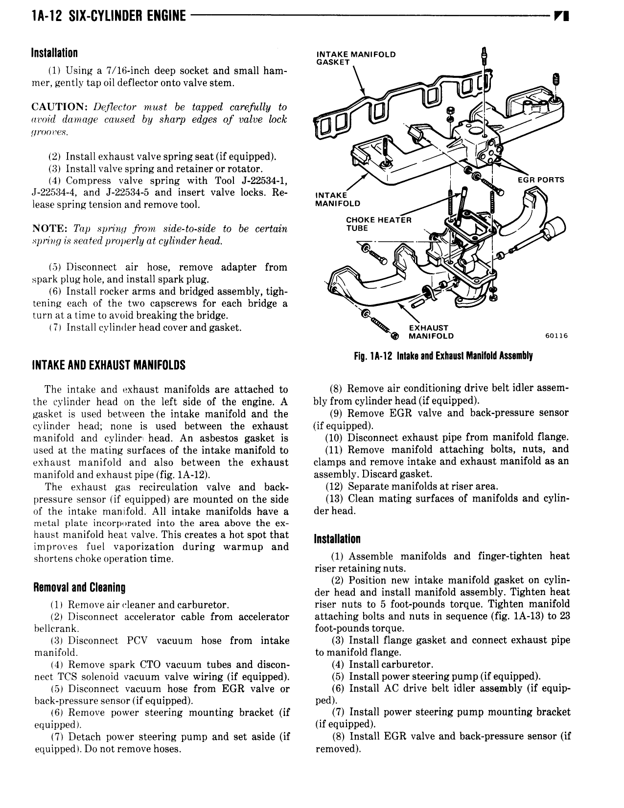
lll l2 SIX CYLINDEN ENGINE VI lllsilllallllll inraxe MAnu 0i o GASKET 1 Using a 7 16 inch deep socket and small ham mer gently tap oil deflector onto valve stem U E Q CAUTION Defiecmr must be tapped carefully to U U Q aroizl damage caused by sharp edges of valve Lock G woo wes x L 2 Installexhaust valvespringseat ifequipped zi I 3 Install valve spring and retainer or rotator Z 4 Compress valve spring with Tool J 22534 1 l l EGR PORTS J 22534 4 and J 22534 5 and insert valve locks Re N AK lease spring tension and remove tool MANIFCN D ci coke l eA1 zn Y NOTE Trip spring from side to side to be certain TUBE spring is seated properly or cylinder hea D x 5 Disconnect air hose remove adapter from I spark plug hole and install spark plug Z A 6 Install rocker arms and bridged assembly tigh tening each of the two capscrews for each bridge a c E turn at a time to avoid breaking the bridge 7 Install cylinder head cover and gasket EXHAUST Q MANir0i n sous n I nhl INTAKE Mm EXHAUST Mmlmlns Flq Il 12 lnlakuml Exh uslM ltndkssn y The intake and exhaust manifolds are attached to 8 Remove air conditioning drive belt idler assem the cylinder head on the left side of the engine A bly from cylinder head ifequipped gasket is used between the intake manifold and the 9 Remove EGR valve and back pressure sensor cylinder head none is used between the exhaust if equipped manifold and cylinder head An asbestos gasket is 10 Disconnect exhaust pipe from manifold flange used at the mating surfaces of the intake manifold to 11 Remove manifold attaching bolts nuts and exhaust manifold and also between the exhaust clamps and remove intake and exhaust manifold as an manifold and exhaust pipe fig 1A 12 assembly Discard gasket The exhaust gas recirculation valve and back 12 Separate manifolds at riser area pressure sensor if equipped are mounted on the side 13 Clean mating surfaces of manifolds and cylin of the intake manifold All intake manifolds have a derhead metal plate incorporated into the area above the ex haust manifold heat valve This creates a hot spot that Insmlmnn improves fuel vaporization during warmup and Shm tens Chckeopemtion timg 1 Assemble manifolds and finger tighten heat riser retaining nuts 2 Position new intake manifold gasket on cylin Mmoval and ummm der head and install manifold assembly Tighten heat 1 Remove aircleaner and carburetor riser nuts to 5 foot pounds torque Tighten manifold 2 Disconnect accelerator cable from accelerator attaching bolts and nuts in sequence fig 1A 13 to 23 hellcrank foot pounds torque 3 Disconnect PCV vacuum hose from intake 3 Install flange gasket and connect exhaust pipe manifold to manifold flange 4 Remove spark CTO vacuum tubes and discon 4 Install carburetor nect TCS solenoid vacuum valve wiring if equipped 5 Install power steering pump ifequipped 5 Disconnect vacuum hose from EGR valve or G Install AC drive belt idler assembly if equip back pressure sensor if equipped ped 6 Remove power steering mounting bracket if 7 Install power steering pump mounting bracket equipped if equipped 7 Detach power steering pump and set aside if S Install EGR valve and back pressure sensor if equipped Do not remove hoses removed