Ford Parts Wiki | GM Parts Wiki
Home | Search | Browse | Marketplace | Messages | FAQ | Guest
|
Technical Service Manual January 1975 |
|
Prev
 Next
Next
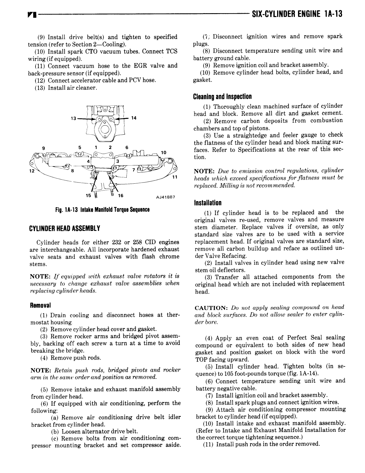
SIX CYLINDER ENGINE IA 13 9 Install drive belt s and tighten to specified 7 Disconnect ignition wires and remove spark tension refer to Section 2 Cooling plugs 10 Install spark CTO vacuum tubes Connect TCS 8 Disconnect temperature sending unit wire and wiring if equipped battery ground cable 11 Connect vacuum hose to the EGR valve and 9 Remove ignition coil and bracket assembly back pressure sensor if equipped 10 Remove cylinder head bolts cylinder head and 12 Connect accelerator cable and PCV hose gasket 13 Install air cleaner Cloanlno and Inspoctlon f W 1 Thoroughly clean machined surface of cylinder 13 i M head and block Remove all dirt and gasket cement l E E 2 Remove carbon deposits from combustion L I chambers and top of pistons 3 Use a straightedge and feeler gauge to check S 5 1 i 2 6 the flatness of the cylinder head and block mating sur ggg 5 w iasles Refer to Specifications at the rear of this sec 2 B I 7 L5 P NOTE Dae to emission control regulations cylinder heads which exceed specijications for flatness must be Y A replaced Milling is not recommended 15 Y is amssv Installation nl mm m 0MT mu s q m 1 If cylinder head is to be replaced and the original valves re used remove valves and measure CYLINDER HEAD ASSEMBLY stem diameter Replace valves if oversize as only standard size valves are to be used with a service Cylinder heads for either 232 or 258 CID engines replacement head If original valves are standard size are interchangeable All incorporate hardened exhaust remove all carbon buildup and reface as outlined un valve seats and exhaust valves with flash chrome derValve Refacing stems 2 Install valves in cylinder head using new valve p p stem oil deflectors N0 1 E if equipped with erhawi valve rowers it is sx Transfer all attached components from the 2 a I 0 cllimge WWW valve Msmblws when original head which are not included with replacement replacing cylinder heads head n CAUTION Do not apply aoaziag compound on noaa 1 Drain cooling and disconnect hoses at ther and block surfaces D0 not allow sealer to enter cylin mostat housing der bore 2 Remove cylinder head cover and gasket 3 Remove rocker arms and bridged pivot assem 4 Apply an even coat of Perfect Seal sealing bly biickmg Of Each Screw a mm at 3 mm m avmd compound or equivalent to both sides of new head breakmg the b dg gasket and position gasket on block with the word 4 Remove push rods TOP facing upwardl 4 5 Install cylinder head Tighten bolts in se g7 552h5 2lL gg Zzjsbolggggfgszlevxljfvggd rocky quence to 105 foot pounds torque fig 1A 1d 6 Connect temperature sending unit wire and 5 Remove intake and exhaust manifold assembly battery negative cable from cylinder head 7 Install ignition coil and bracket assembly 6 If equipped with air conditioning perform the 8 Install spark plugs and connect ignition wires following 9 Attach air conditioning compressor mounting a Remove air conditioning drive belt idler bracket to cylinder head if equipped bracket from cylinder head 10 Install intake and exhaust manifold assembly b Loosen alternator drive belt Refer to Intake and Exhaust Manifold Installation for c Remove bolts from sir conditioning com the correct torque tightening sequence pressor mounting bracket and set compressor aside 11 Install push rods in the orderremoved