Ford Parts Wiki | GM Parts Wiki
Home | Search | Browse | Marketplace | Messages | FAQ | Guest
|
Technical Service Manual January 1975 |
|
Prev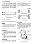
 Next
Next
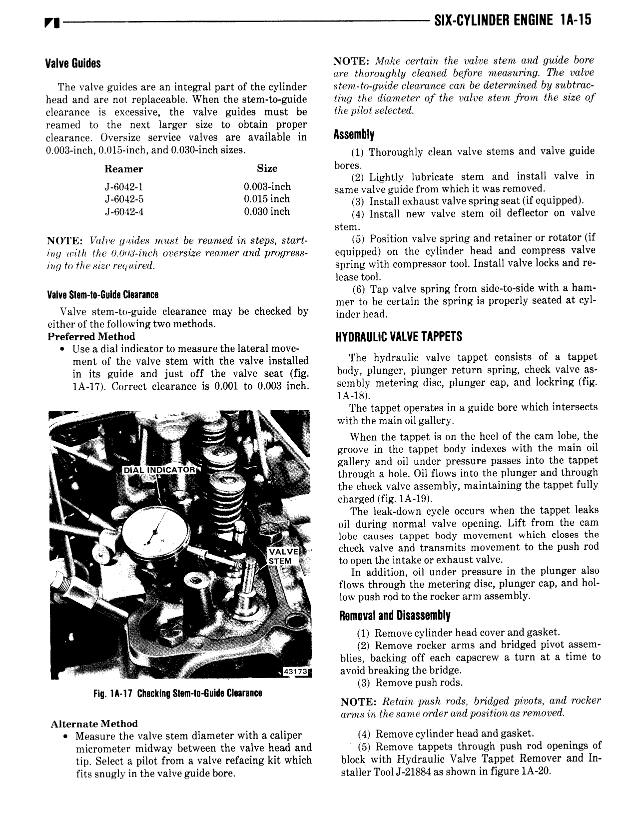
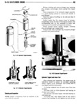
VI S X l YL NI ER ENGINE IA 15 Vilvq Guida NOTE Make certain the valve stern and guide bore are thoroughly cleaned before measumrig The valve The valve guides are an integral part of the cylinder stem to guide clearance can be determined by subtrac head and are not replaceable When the stem to guide ting the diameter ofthe valve stem from the size of clearance is excessive the valve guides must be fhe11il tseIected reamed to the next larger size to obtain proper clearance Oversize service valves are available in NS l IlIly 0 003 inch 0 015 inch and 0 030 inch sizes 1 Thoroughly dean Valve Stems and valve guide Reamer Size heres 2 Lightly lubricate stem and install valve in J 6042 1 0 003 h same valve guide from which it was removed J 6042 5 0015 Mh 3 Install exhaust valve spring seat if equipped J 6042 4 0 030 h 4 Install new valve stem oil deflector on valve stem NOTE Wire griides must be reamed in steps start 5 Position valve spring and retainer or rotator if my with the I v a i1ic i oversize reamer and progress equipped on the cylinder head and compress valve my to filesize required spring with compressor tool Install valve locks and re lease tool yam s m m md mmm 6 Tap valve spring fromside to side with a ham mer to be certain the spring is properly seated at cyl Valve stem to guide clearance may be checked by inderhgad either of the following two methods Preferred Metnrrl llvmuullc VALVE TAPPETS Use a dial indicator to measure the lateral move ment of the valve stem with the valve installed The hydraulic ValV tappet clmsists of 6 tappet in its guide and just off the valve ecec rig body plunger plunger return spring check valve as 1A 17 Correct clearance is 0 001 to 0 003 inch iingy metering disc plunger cap and lvekring fig 7 V The tappet operates in a guide bore which intersects A i with the main oil gallery V Y xl I F5 y I k Q When the tappet is on the heel of the cam lobe the i groove m the tappet body indexes with the maln oll DIALINDICATOR gallery and oll under pressure passes into the tappet i h through a hole Oil flows into the plunger and through i the check valve assembly maintaining the tappet fully L rf charged fig IA 19 Q A 7 The leak down cycle occurs when the tappet leaks i j oil during normal valve opening Lift from the cam lj lobe causes tappet body movement vvlnclr closes the V VA check valve and transmits movement to the push rod ie i V M sY M to open the intake or exhaust valve V w Jil In addition oil under pressure in the plunger also W r Vi flows through the metering disc plunger cap and hol rr ih T low push rod to the rocker arm assembly Removal and Dlsassnmlnly C ig ag J l Y 1 Remove cylinder head cover and gasket V t t V l 4 2 2 Remove rocker arms and bridged pivot assem V blies backing off each capscrew a turn at a time to Y f oclug avoid breaking the bridge 3 Remove push rods Flu IMT chanting stun la GuId Clunnca NOTE Retain pus i rods bridged pivots and rocker arms in the same order and positicm as removed Alternate Method Measure the valve stem diameter with a caliper 4 Remove cylinder head and gasket micrometer midway between the valve head and 5 Remove tappets through push rod openings of tip Select a pilot from a valve refacing kit which block with Hydraulic Valve Tappet Remover and In fits snugly in the valve guide bore staller Tool J 21884 as shown in figure IA 20