Ford Parts Wiki | GM Parts Wiki
Home | Search | Browse | Marketplace | Messages | FAQ | Guest
|
Technical Service Manual January 1975 |
|
Prev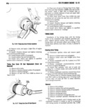
 Next
Next
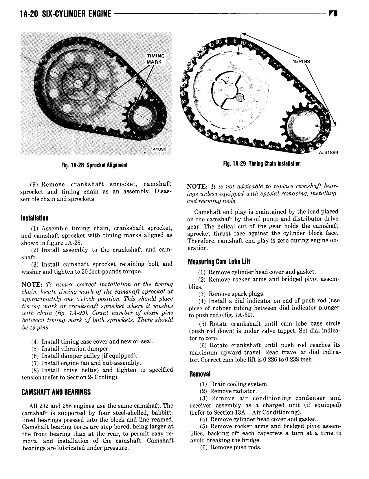
lll 20 SIX GYLINIIEII ENGINE VI J K Z Wifi J Timms V is i Y r MARt V isems t 4 I t V I I I e g Q V 4 e r h gsi res nn si I gnitv an v 4 I I J i it anon e e EEN c tc V 2 Ar il n ii Q Liv e V e 4 g fha 3 I e uses eegs V Ataiaso nm 1A z3 gpmm Mtlnmsqn Flg tA 29 Tlnlng tinaln Installation lg Remgve Ij 1 tt Sprocket by mIg NOTE It is not advisable ee replace camshaft bear Spmc et an ummg C rn as an assem y lsasl ings unless equipped with special removing installing semble chain and sprockets and rmming tools Camshaft end play is maintained by the load placed lnsmmlon on the camshaft by the oil pump and distributor drive 1 Assemble timing chain crankshaft sprocket E9a The helical cut of the BBB holds the camshaft and camshaft sprocket with timing marks aligned as sprvcket thrust face aswnst the cylmder block fate shown in figure 1A 28 Therefore camshaft end play is zero during engine op 2 Install assembly to the crankshaft and cam 9ml l h shaft 3 Install camshaft sprocket retaining bolt and Musllrlllg cm Lam l lll Washer and tlghteh W 50 f 0t P0 dS t t l 1 Remove cylinder head cover and gasket k d d t NOTE To assure correct installation of the timing Ims 2 Remove mc er arms and bm ge PWD assem chain locate timing mark of the camshaft sprocket at Is Remove spark plugs approximately one oclock position This should place III Install s dial indicasor Im end DI push md use hwg not nf mtsteft Svmtttt rtw it wigs piece er rubber tubing between enei indicator plunger with chain Mtg 144 29 Count number of chain pins to II d pus ro fig 1A 30 between timing mark of both sprockets There should be I5 pim 5 Rotate crankshaft until cam lobe base circle push rod down is under valve tappet Set dial indica 4 I I II d 1 II tortozero I i mm timing case cover an new Ol Sea 6 Rotate crankshaft until push rod reaches its 5 Install vibration damper d I d I ISI IIIsIaII damper pIIIIeyIIf qIIIpIIed I maximum upwar trave Read travel at ia indica I Install sngme fan and hub assembly tor Correct cam lobe lift is 0 226 to 0 2381nch 8 Install drive belt s and tighten to specified I tension refer to Section 2 Cooling naman 1 Drain cooling system GAMSNAFI ANI BEARINGS 2 Remove radiator 3 Remove air conditioning condenser and All 232 and 258 engines use the same camshaft The receiver assembly as a charged unit if equipped camshaft is supported by four steel shelled babbitt refer to Section 13A Air Conditioning lined bearings pressed into the block and line reamed 4 Remove cylinder head cover and gasket Camshaft bearing bores are step bored being larger at 5 Remove rocker arms and bridged pivot assem the front bearing than at the rear to permit easy re blies backing off each capscrew a turn at a time to moval and installation of the camshaft Camshaft avoid breakingthe bridge bearings are lubricated under pressure 6 Remove push rods