Ford Parts Wiki | GM Parts Wiki
Home | Search | Browse | Marketplace | Messages | FAQ | Guest
|
Technical Service Manual January 1975 |
|
Prev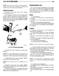
 Next
Next
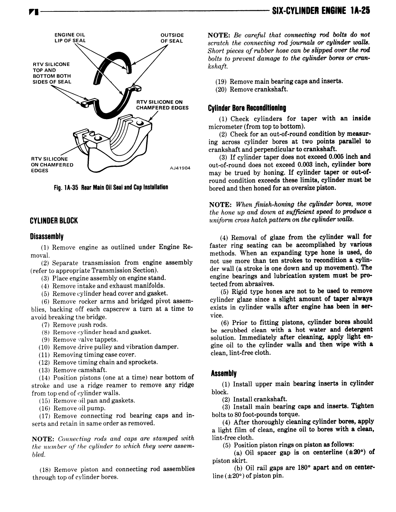
VI SIX CYLINDER EIGIIE IA Z5 ENG O 0Ui i E NOTE Be carefal that connecting rod bolts do not Sm SEAL scratch the connecting me jomon or mum wom Short pieces ofmbber hose can be slipped over the rod RW SILICONE bolts to prevent damage to the cylinder bores or cran ror Ann kshafb ao r roM som s E SEA 0 19 Remove main bearing caps and inserts 20 Remove crankshaft wrv siucons on AMFE E S Gyllndar Bm Il t nillll nIn 1 Check cylinders for taper with an inside micrometer from top to bottom 2 Check for an out of round condition by measur ing across cylinder bores at two points parallel to crankshaft and perpendicular to crankshaft srv sn nc0r 1z 3 If cylinder taper does not exceed 0 005 inch and gg zgnmrsnso Aww our of ound does notexceed 0 003 inch cylinder bore may be trued by honing lf cylinder taper or out of round condition exceeds these limits cylinder must be ill W35 ll ml ml Wl Will ull lm ll il bored and then honed for an oversize piston NOTE When inislohoning the cylinder bores move the hone np and down at sufficient speed to produce a CYLINDER BLOCK uniform cross hatch pattern on the cylinder walls umssambli 4 Removal of glaze from the cylinder wall for 1 Remove engine as outlined under Engine Re faster ring seating can be accomplished by various moval methods When an expanding type hone is used do 2 Separate transmission from engine assembly 0 use 0 than WD 8 k to i 9 diti Ylin refer toappropriate Transmission Section i i wall 8 8U 0k is 0 down Bild UP m V m n l The 3 Place engine assembly on engine stand engine bearings and lubrication system must be pro 4 Remove intake and exhaust manifolds tected from abrasives 5 Remove cylinder head cover and gasket 5 Rigid WW i 10 8 BW mt to i used W i 1 0V 6 Remove rocker arms and bridged pivot assem 0yii1 l i 1 Slim i 0 iiBi it Bmoimt of UN lW Y blies backing off each capscrew a turn at a time to exists in Yii i wells Ute 8i hu b in WF avoid breaking the bridge vice 7 Remove push rods 6 Prior to fitting pistons cylinder bores should 8 Remove cylinder head and gasket be scrubbed clean with a hot water and detergent 9 Remove valve tappets solution Immediately after cleaning apply light en 10 Remove drive pulley and vibration damper zine oil to the cylinder walls and then wipe with a 11 Removing timing case cover clean lint free cloth 12 Remove timing chain and sprockets 13 Remove camshaft 14 Position pistons one at a time near bottom of humbly stroke and use a ridge reamer to remove any ridge 1 Install upper main bearing inserts in cylinder from top end of cylinder walls block 15 Remove oil pan and gaskets 2 Install crankshaft 16 Remove oil pump 3 Install main bearing caps and inserts Tighten 17 Remove connecting rod bearing caps and in boltsto80foot pounds torque serts and retain in same order as removed 4 After thoroughly cleaning cylinder bores apply a light film of clean engine oil to bores with a clean NOTE Connecting rods and caps are stamped with lint free cloth llze number of the cylinder to which they were ussem 5 Position piston rings on piston as follows bled a Oil spacer gap is on centerline k20 of piston skirt 18 Remove piston and connecting rod assemblies b Oil rail gaps are 180 apart and on center through top of cylinder bores line t20 of piston pin