Ford Parts Wiki | GM Parts Wiki
Home | Search | Browse | Marketplace | Messages | FAQ | Guest
|
Technical Service Manual January 1975 |
|
Prev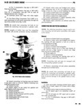

 Next
Next
SlX CYL NDER ENGINE 1A Z1 d N0 1 compression ring gap is 180 e20 journals If wear patterns or damage to any of the from No 2 compression ring gap with at least 30 be above mentioned components indicate the probability tween each ring gap of a misaligned connecting rod check rod alignment 3 Lubricate piston and rings with clean engine Misaligned or bent rods mustbe replaced oil 4 Usa Piston Ring Compressor Tool J 5601 to in Side Dlaaranca Nlaasuramnt stall connecting rod and piston assemblies through the mp or the cylinder bores fig 1A 36 1 Slide snug fitting feelengauge between connec ting rod and crankshaft rod Journal flange Correct N TE gg cllrejul tha conmctmg md bolts do mt clearance is 0 00 to 0 014 inch Replace connecting rod scratch the ctnmectiny rod journals or cylinder walls if 1 19 Clearance 5 tt SP lfl aU nS Lengths of rubber hose over the connecting rod bolts will provide protection during installation clmmmmg mm marinus Th t d b t l b k d 5 Install connecting rod bearing caps and inserts alum lui y B c i0n tgggngs are S ee an e m the Same mide as r m V d Tlghmn tammg nuts Each bearing is selectively fitted to its respective m 28 f p d rq journal to obtain the desired operating clearance In 6 Insuflll ml van usmg mw gaskets and Seam production the select fit is obtained by using various T gh dmm plugsecurelyy sized color coded bearing inserts as shown in the gaslliet iind v d r head bearing fitting chart The bearing color code appears sa pus ro s th d Hh t 9 Install rocker arms and bridged pivot assem on ee geo emser Ehesi ughienmg eilch Of the capscrews 8 wm at a NOTE Bearing size is not strtrnpetl on inserts used in time to avoid breaking the bridge pmductimh 10 Installcylinder head coverand gasket g g 11 Fil the cmnkcase with new Oi 0 specified The rod journal size is identified in production by a dipstick level color coded paint mark on the adjacent cheek or counltezweighthtoward th flanggd rea end of the cran s aft T e co or co es use to in icate journa BUNNEGTING mms size are shown in the bearing fitting chart When required different sized upper and lower The Fonmictmg rl dS are nodular mm balaiiced bearing inserts may be used as a pair therefore a msemhhes with bearing inserts at the crankshaft Jour tandard size insert is sometimes used in combination nal ind A Squirt hole in the crankshaft end provides ivith a 0 001 inch undersize insert to reduce clearance lubrication for ihe camshaft lobes distributor drive 00005m h gear cylinder walls and piston pins The squirt hole must face the camshaft when the connecting rod is in NOTE Newer use a pair of bearing msens with mm stalled r The piston pin is a 2 000 pound press fit Replace Hlu 0 001 Mich diyerence mmza any rod that requires little effort to install piston Example pins Correct Incorrect Misaligned or bent connecting rods will cause Upper Standard Standard abnormal wear on pistons piston rings cylinder walls Lower 0 001 inch 0 002 inch undersize connecting rod bearing or crankshaft connecting rod undersize Gannactlng Ilurl Roaring Flltlng Chart Iiranmall tnmmlnr Rui Journal hiring war me Dam md llimmr In Yellow 2 0955to zimststsndard vonow Standard Yellow Standard Orange 2 0948to2o94 0 0o07 undersize vellnw standard Black 001 tncn undersize Black 2 0941to2osa4 o 0014L nd tssze Black 001 Inch undersize Black 001 men unuersize Red 20B55tn2 084B 0 010undersize Red 010 lnctt undersize Red oi0 tnon undersize 50261