Ford Parts Wiki | GM Parts Wiki
Home | Search | Browse | Marketplace | Messages | FAQ | Guest
|
Technical Service Manual January 1975 |
|
Prev
 Next
Next
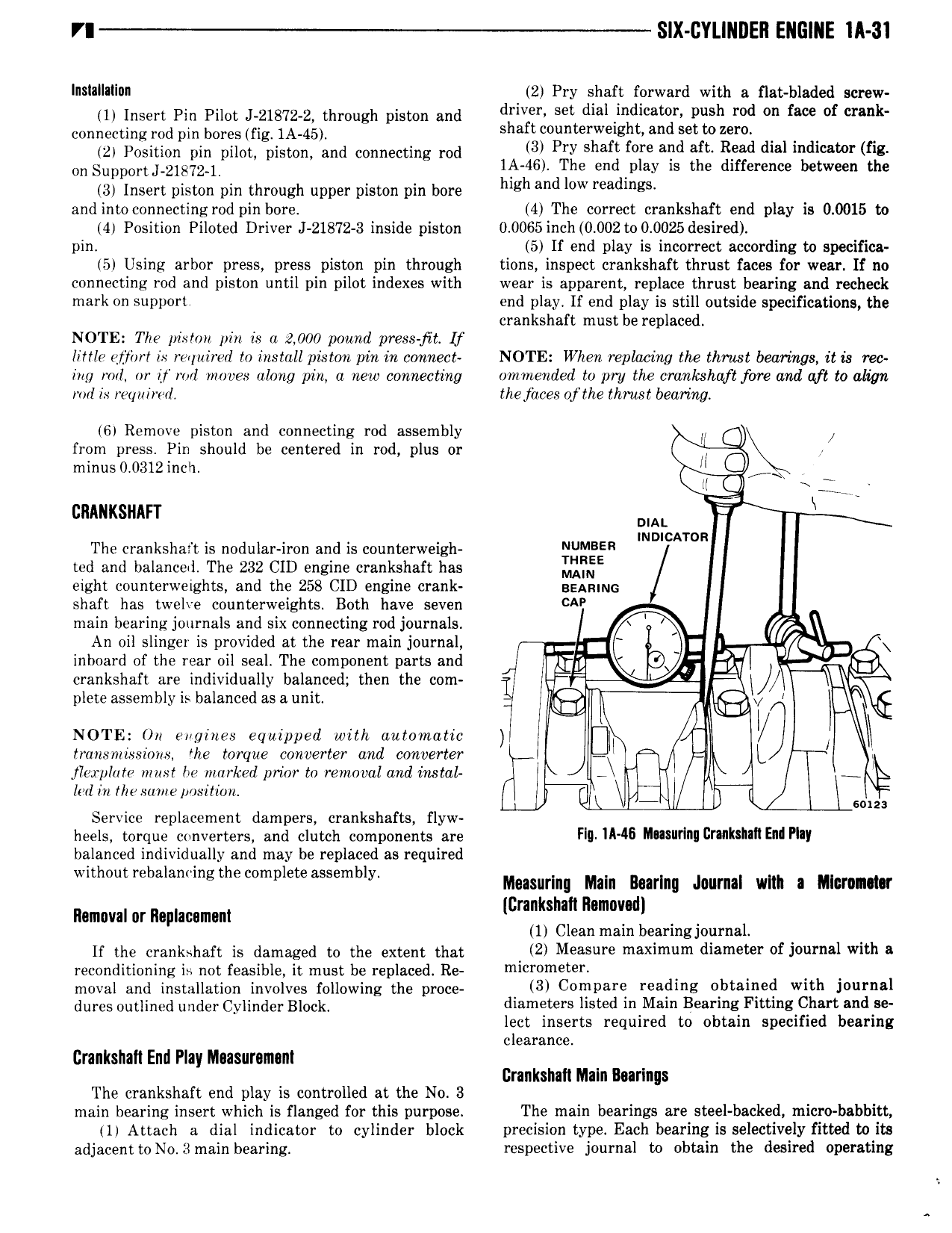
S X GYL NDEll ENGINE ll 31 Installation 2 Pry shaft forward with s flat bladed screw 1 Insert Pin Pilot J 21872 2 through piston and driven set dei mdl ai push md fm f crank connecting md pm bores fig 1A 45 shaft counterweight and set tozero I 2 Position pin pilot piston and connecting rod 3 Ply Shaft f l alld air RPM dial lndlcamr fi on Suppm tJ 21872 1 lli 46 The end rplay is the difference between the 3 Insert piston pin through upper piston pin bore high and l W Yeadmgx and intoconnecting rod pin bore 4 The correct crankshaft end play is 0 0015 to 4 Position Piloted Driver J 21872 3 inside piston 0 0065incb 0 002 to 0 0025 desired pin 5 If end play is incorrect according to specifica 5 Using arbor press press piston pin through tions inspect crankshaft thrust faces for wear If no connecting rod and piston until pin pilot indexes with wear is apparent replace thrust bearing and recheck mark on support end play If end play is still outside specifications the crankshaft must be replaced NOTE The piston pin is u 2 000 pound press jit lf li ttle ejtthrt is required to install piston pin in wnnect NOTE When replacing the thrust bearings it Ls rec ing mil or it ror1 moves along pin a new connecting onrrnended to Wy the l lwl 8h fi fore and ttf to 0liW rorl ix reqziirwl the jaces ofthe thrust bearing 6 Remove piston and connecting rod assembly ri from press Pin should be centered in rod plus or V minus 0 0312 inch f QQ cninxsnirr l ii om The crankshaft is nodular iron and is counterweigh NUMBH INDICATOR ted and balanced The 232 CID engine crankshaft has L j f eight counterweights and the 258 CID engine crank BEARING shaft has twelve counterweights Both have seven CA main bearing journals and six connecting rod journals An oil slinger is provided at the rear main journal I inboard of the rear oil seal The component parts and 0 crankshaft are individually balanced then the com F plete assembly is balanced as a umt Q5 I Q NOTE On engines equipped with automatic I I transmissions the torque converter and converter jlorplote must he marked prior to removal and instal I l lad in r ie some posi limi y hl I 60123 Service replacement dampers crankshafts flyw heels torque converters and clutch components are Fill iI i M liYliiII i liN miE i Pill balanced individually and may be replaced as required without rebalammg the complete assembly Maasurlng mln Burl Jwmal wm I Ulucmmr llamoval or llaplacsmant lcmkshm mmmjodl 4 1 Clean mam bearing journal If the crankshaft is damaged to the extent that 2 M 8 i 9 maximum diameter of ivurnei with 3 reconditioning ii not feasible it must be replaced Re mi V m i 9i moval and installation involves following the proce 3 C0 D3F6 reading Gbtitined with j0 1l l l dnres Onrnnnd under Cylinder B 0ck diameters listed in Main Bearing Fitting Chart and se lect inserts required to obtain specified bearing clearance Crankshaft End Play Measurement Crankshaft Maln Burlngs The crankshaft end play is controlled at the No 3 main bearing insert which is flanged for this purpose The main bearings are steel backed micro babbitt ll Attach a dial indicator to cylinder block precision type Each bearing is selectively fitted to its adjacentto No 3main bearing respective journal to obtain the desired operating