Ford Parts Wiki | GM Parts Wiki
Home | Search | Browse | Marketplace | Messages | FAQ | Guest
|
Technical Service Manual January 1975 |
|
Prev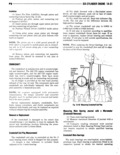
 Next
Next
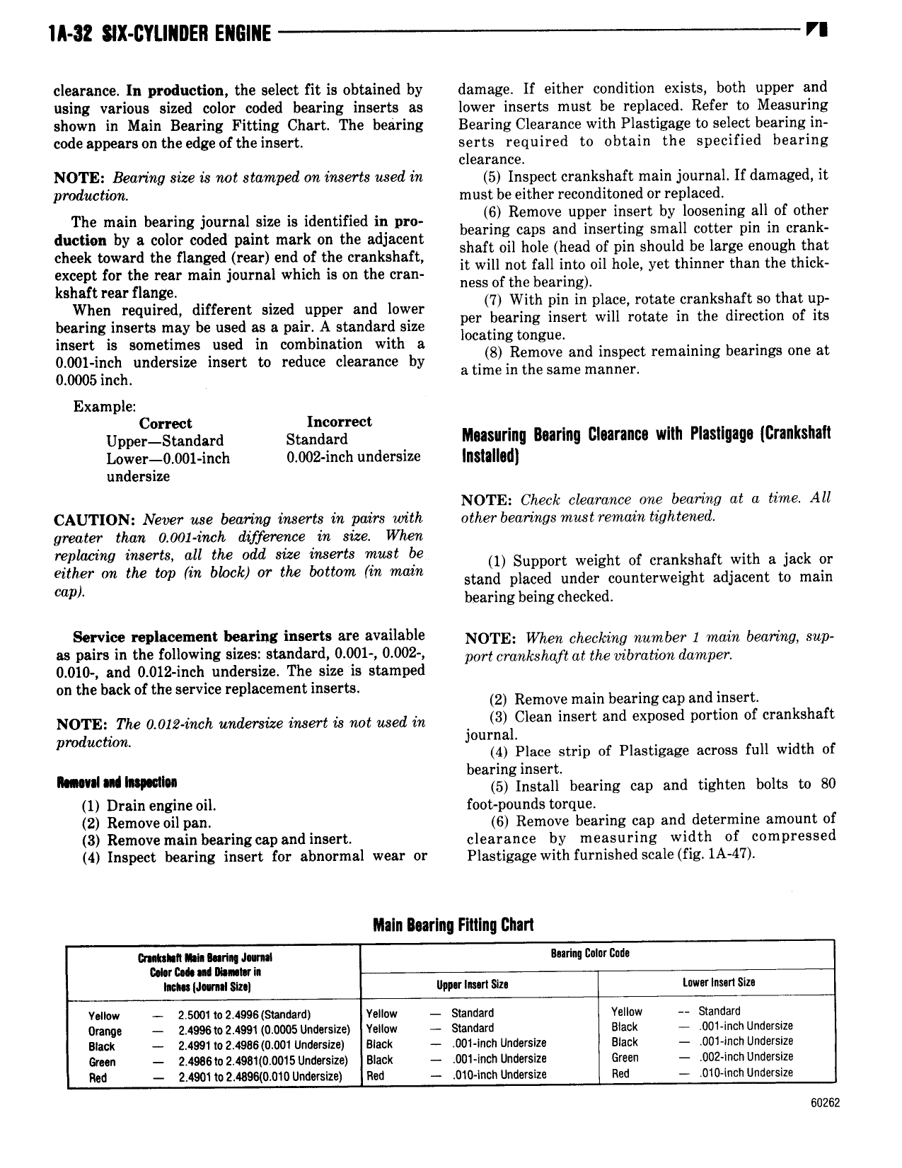
ll 32 SIX CYLINDER EIIEIIIE VI clearance In production the select fit is obtained by damage If either condition exists both upper and using various sized color coded bearing inserts as lower inserts must be replaced Refer to Measuring shown in Main Bearing Fitting Chart The bearing Bearing Clearance with Plastigage toselect bearing in code appears on the edge of the insert serts required to obtain the specified bearing clearance NOTE Bearing size is not stamped on inserts used in 5 Inspect crankshaft main journal If damaged it pmductwn must be either reconditoned or replaced The main nennng ennnnn nn nn identified nn nn be QQ R m V ng P jgj Sr y Sg jp i l Of Ogg duction by a color coded paint mark on the adjacent ar Q cap msg g a C0 p m or shaft oil hole head of pin should be large enough that h k h fl g d d k h f it wan not nu into do in le et thinner than the an le except for the rear main journal which is on the crsn 0 Y kshaft wu flange ness of the bearing When required dnnenene sized upper and lower fj WM gm g ey rg g j kSggj c 2t g g bearing inserts may be used as a pair A standard size mj Eear gg mer WI ro a B In E E mn I B insert is sometimes used in combination with a Ow ggk ngu d t b t 0 001 inch undersize insert to reduce clearance by atisieinilrlosjsymgmziic remgmmg Earmgs mea 0 0005 inch Example Correct Incorrect Upper Standard Standard Imsunnq Imrlng Clearance wlth Plasllgaga Crankshaft L0wer 0 001 inch 0 002 inch undersize I l II3 I undersize NOTE Check clearance one bearing at a time All CAUTION Never use bearing inserts in pairs with other bearings mustremain tightened greater than 0 001 inch difference in size When replacing inserts all tim odd size inserts must be 1 Support weight of crankshaft with a jack or gh rm the um W bhwk or the bottom m mam stand placed under counterweight adjacent to main P bearingbeingchecked S vi i m bww i r M v il bl Nora when eneexang number 1 mm bednng dep as pairs in the following sizes standard 0 Q01 0 002 WH crankshaft at the bmt m damper 0 010 and 0 012 inch undersize The size is stamped on the back of the service replacement inserts 2 Remove main bearing cap and insert N0 I E The 0 0l2 wh undersize Mer is not Med in 4 3 Clean insert and exposed portion of crankshaft pmdMmm journal 4 Place strip of Plastigage across full width of bearing insert h mm 5 Install bearing cap and tighten bolts to 80 1 Drain engine oil foot pounds torque 2 Remove oil pan 6 Remove bearing cap and determine amount of 8 Remove rnain bearing cap and insert clearance by measuring width of compressed 4 Inspect bearing insert for abnormal wear or Plastigage with furnished scale fig 1A 47 Maln Iurlng Filling Chart mmnnnunnqaum rM l r we uhainanmn lion J mI Sin Im lmrl Siu Lwnr lnun Sim vom 2 soo1w2 ees4s annnm venow svanuam Vsllow sxdnuam Orange 2 4essm2 4ee1 40 00osum1svsnze vennw Standard slack 001 anon unadrnze num 2 4991to2 4986 0 001UndMsize suck 001 men Undersizc Blank 001 mct Undersnze omn 2 4sc6e 2 4sst 0 00is unuusize slack 0ni men unuersizd Green 002 menunuevsaze Red Z 4901lo2 489B 0 0 Undersize Rod 010 Inch Undersize Red 010 inoh undersize 60262