Ford Parts Wiki | GM Parts Wiki
Home | Search | Browse | Marketplace | Messages | FAQ | Guest
|
Technical Service Manual January 1975 |
|
Prev

 Next
Next
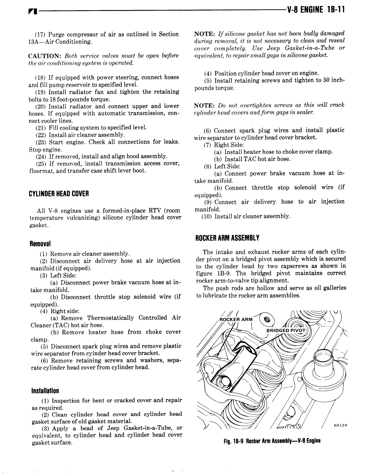
8 ENGINE III II 17 Purge compressor of air as outlined in Section NOTE Ifsilicone gasket has not been badly damaged 13AiAir Conditioning during removal it is not necessary to clean and reseal cover completely Use Jeep Gasket in a Tube or CAUTION Both service valves must be open before e uivaknt to repairsmallgaps in silicone gasket Q the air conditioning system is operated 4 Position cylinder head cover on engine 18 If equipped with power steering connect hoses and fill pump reservoir to specified level Ouigslgiwgg retaining Screws and tighten to 50 Inch 19 Install radiator fan and tighten the retaining p q bolts to 18 foot pounds torque 20 Install radiator and connect upper and lower NOTE Do not overtighten screws as this will crack hoses Il equipped with automatic transmission con cylinder head covers andform gaps in sealer nect cooler lines 21 Flncmling system to specmedlevel 6 Connect spark plug wires and install plastic 22 Install mr Cleaner assembly wire separator to cylinder head cover bracket 23 Start engine Check all connections for leaks 7 Right Side Stop engine a Install heater hose to choke cover clamp 24 If removed install and alignhood assembly b Install TAC hot air hose Z5 If removed install transmission access cover 8 Left Side floormatand transfercaseshiftlever boot a Connect power brake Vacuum hose at in take manifold b Connect throttle stop solenoid wire if IZYLINIIEII NEAD DDVEII equippedy 9 Connect air delivery hose to air injection All V 8 engines use a formed in place RTV room manifold temperature vulcanizing silicone cylinder head cover 10 Install air cleanerassembly gasket IIDIIKEII MIM ASSEMBLY Removal 1 Remove air cleaner assembly The intake and exhaust rocker arms of each cylin 2 Disconnect air delivery hose at air injection der P 0 0 bridged D V0 dSS mblY which 15 secured manifold if equipped to the cylinder head by two capscrews as shown in 3 Left Side figure 1B 9 The bridged pivot maintains correct a Disconnect power brake vacuum hose at in Ydcksr al m i V lV UP llZ take manifold T e push rods are hollow and serve as oil galleries b Disconnect throttle stop solenoid wire if t0l b i08 the rocker 81 111 8SS mblI S4 equipped 4 Right side gy U a Remove Thermostatically Controlled Air ARM Cleaner TAC hot air hose U l 6 I clamp b Remove heater hose from choke cover QR 2GE 5 Disconnect spark plug wires and remove plastic V l wire separator from cyinder head cover bracket dl y 1 6 Remove retaining screws and washers sepa rate cylinder head cover from cylinder head v W J Y x lnslallallnn 1 Inspection for bent or cracked cover and repair as required 2 Clean cylinder head cover and cylinder head W 4 gasket surface of old gasket material E 3 Apply a bead of Jeep Gasket in a Tube or N 2 equivalent to cylinder head and cylinder head cover gasket surface Flu IB 9 R uk r Ann AmmhIy V l Enqlnn

 Next
Next