Ford Parts Wiki | GM Parts Wiki
Home | Search | Browse | Marketplace | Messages | FAQ | Guest
|
Technical Service Manual January 1975 |
|
Prev

 Next
Next
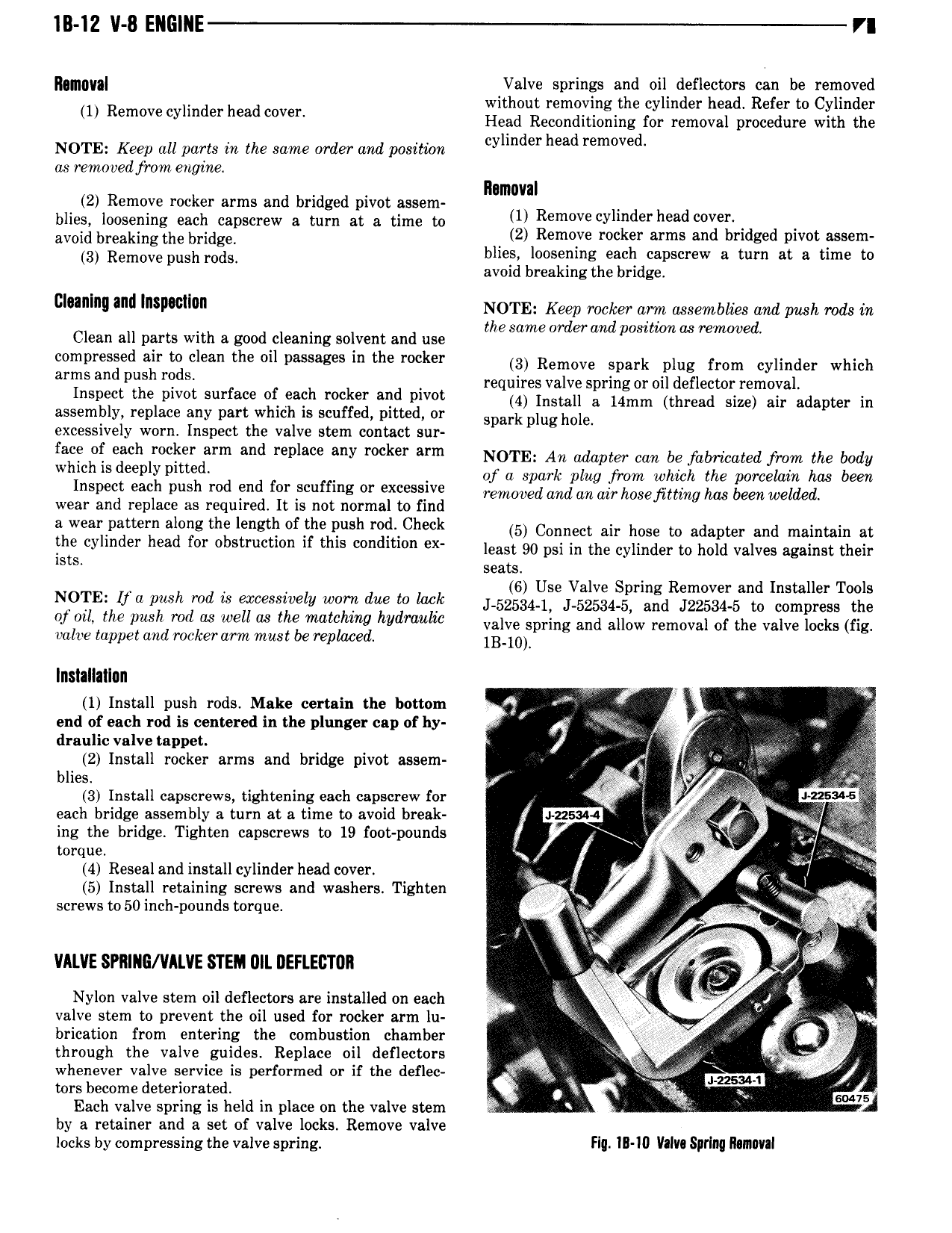
IB IZ V 8 ENGlI E VI Ikgmygl Ialve springs and oi diefleatoxns be zjernow ed wit out removingt e cy in er ea e er to y in er 1 Remove cylinder head cover Head Reconditioning for removal procedure with the NOTE Keep all ports in the same order and positwkm cylmder head removed as remo ved from engine llamaval 2 Remove rocker arms and bridged pivot assem blies loosening each capscrew a turn at a time to U Remove yl d i head V avoid breaking the bridge V 2 Remove rocker arms and bridged pivot assem 3 Remove nnsh i ooisI blies loosening each capscrew a turn at a time to avoid breaking the bridge cl l V and lnsllomlun NOTE Keep rocker arm assemblies aml push rods in lh d ml Clean all parts with a good cleaning solvent and use esame or era poshmmu removed 2g Ii i u i I yII I a the Oil i the rocker 3 Remove spark plug im synmsss which I I d fl t I Inspect vhs slvss surface ct each rocker end psvsl q ffi f Q i nj i Q f Q mam n assembly replace any part which is scuffed pitted or shank ning hoie excessively worn Inspect the valve stem contact sut face ot each rocker arm and replace any rocker arm NOTE An adapter can he fabricated fiom me body Whmhls deeply pm ed of a spark plug from which the porcelain has been Inspect each push rod end for scuffing or excessive Teomooed and aa ai hosefimng has been welded wear and replace as required It is not normal to find l a wear pattern along the length of the push rod Check 5 Connect an hose in adapter and innintnin nt ih cylinder head for obstruction if this condition ex lease 90 nai in the eyiinder to hoid vnives against their S S seats 6UVlS R d tallTl N9TE If Mh md is ercmvelv www due to IM i si5i4 1 ei z 4 ir sid ililziiilsais gdmpgssogiz of mli the Push md Us well as the matching hydmulw valve spring and allow removal of the valve locks fig valve tappet and rocker arm must be replaced iB i Installation ea 1 Install push rods Make certain the bottom Q I x I end of each rod is centered in the plunger cap of hy Q V draulic valve toppet 7 W Me y I 3 2 Install rocker arms and bridge pivot assem I blies 5 f i 3 Install capscrews tightening each capscrew for I o I 225 I each bridge assembly a turn at a time to avoid break 1 axes Whoo ing the bridge Tighten capscrews to 19 foot pounds T g i Q torque I oj 2 4 Reseal and install cylinder head cover as I il T 5 Install retaining screws and washers Tighten 1 Q V I screwsto50inch pounds torque ei I a gh it g l I v 1I4v s i i VALVE SPRING VILVE STEM UII DEFLECTOR s g E I I I x Nylon valve stem oil deflectors are installed on each q 4 se valve stem to prevent the oil used for rocker arm lu V I brication from entering the combustion chamber I 3 through the valve guides Replace oil deflectors Q E vi g whenever valve service is performed ss is use series ga e liirmm jj tors become deteriorated 1 I so 75 Each valve spring is held in place on the valve stem of A by a retainer and a set of valve locks Remove valve locks by compressing the valve spring FII III I0 Valv Spflllq MIIIIWII

 Next
Next