Ford Parts Wiki | GM Parts Wiki
Home | Search | Browse | Marketplace | Messages | FAQ | Guest
|
Technical Service Manual January 1975 |
|
Prev

 Next
Next
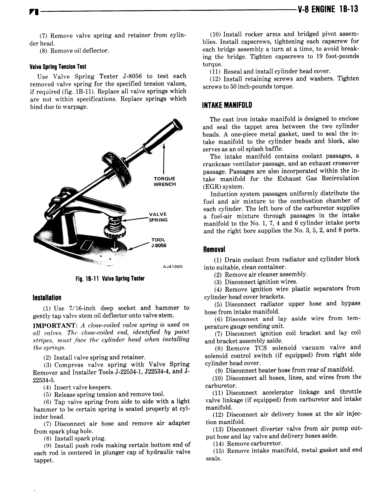
r v B ENGINE 1B 13 7 Remove valve spring and retainer from cylin 10 Install rocker arms and bridged pivot assem der head blies Install capscrews tightening each capscrew for 8 Remove oil deflector each bridge assembly a turn at a time to avoid break ing the bridge Tighten capscrews to 19 foot pounds llaIv S rln Tmsinn Tm torque Us calve Spring Tester J 8056 to test each lll Resealand ipgtallcylinder head cove 12 Install retaining screws and washers Tighten removed valve spring for the specified tension values t 50in h d t if required fig IB 11 Replace all valve springs which screws 0 C ipmm S 0rque are not within specifications Replace springs which bind due to warpage INTAKE MANIFOLD The cast iron intake manifold is designed to enclose and seal the tappet area between the two cylinder i heads A one piece metal gasket used to seal the in take manifold to the cylinder heads and block also serves as an oil splash baffle The intake manifold contains coolant passages a crankcase ventilator passage and an exhaust crossover passage Passages are also incorporated within the in 1 take manifold for the Exhaust Gas Recirculation EGR system e Induction system passages uniformly distribute the fuel and air mixture to the combustion chamber of each cylinder The left bore of the carburetor supplies 6 gtgllmg a fuel air mixture through passages in the intake ij manifold to the No 1 7 4 and 6 cylinder intake ports t and the right bore supplies the No 3 5 2 and B ports mm 2 mw Ramuval 1 Drain coolant from radiator and cylinder block Vi A 5 into suitable clean container 2 Remove air cleaner assembly Fl ll ll vm Sm nm 3 Disconnect ignition wires 4 Remove ignition wire plastic separators from IIISIIIIIIIOII cylinder head cover brackets 1 Use 7 16 inch deep socket and hammer to 5 Dl cmmect mldiamr upper hose and bypass gently tap valve stem oil deflector onto valve stem lwse fr 1 k mamf ld 6 Disconnect and lay aside wire from tem IMPORTANT A close coiled valve spring is used on Parature gauge Sendingunit all l S Thr l Se cml d dmmfled bV PM 7 Disconnect ignition coil bracket and lay coil stnpest must face the cylinder head when mstallmg and bracket assembly aSid PS1mW 8 Remove TCS solenoid vacuum valve and 2 Install valve spring and retainer solenoid control switch if equipped from right side 3 Compress valve spring with Valve Spring cylinder head cover Remover and Installer Tools J 22534 1 J22534 4 and J 9 Disconnect heater hose from rear of manifold 22534 5 10 Disconnect all hoses lines and wires from the 4 Insert valve kee ers carburetor 5 Release spring tldnsion and remove tool ll Disconnect accelerator linkage and throttle 6 Tap valve spring from side to side with a light valve linkage if equipped from carburetor and intake hammer to be certain spring is seated properly at cyl manifold indgr head 12 Disconnect air delivery hoses at the air injec 7 Disconnect air hose and remove air adapter tion manifold from spark plug hole 13 Disconnect diverter valve gom airdpump out 8 Install spark plug put hose and lay valve and delivery oses asi e 9 Install push rods making certain bottom end of 14 Remove carburetor each rod is centered in plunger cap of hydraulic valve 15 Remove intake manifold metal gasket and end tappet seals

 Next
Next