Ford Parts Wiki | GM Parts Wiki
Home | Search | Browse | Marketplace | Messages | FAQ | Guest
|
Technical Service Manual January 1975 |
|
Prev

 Next
Next
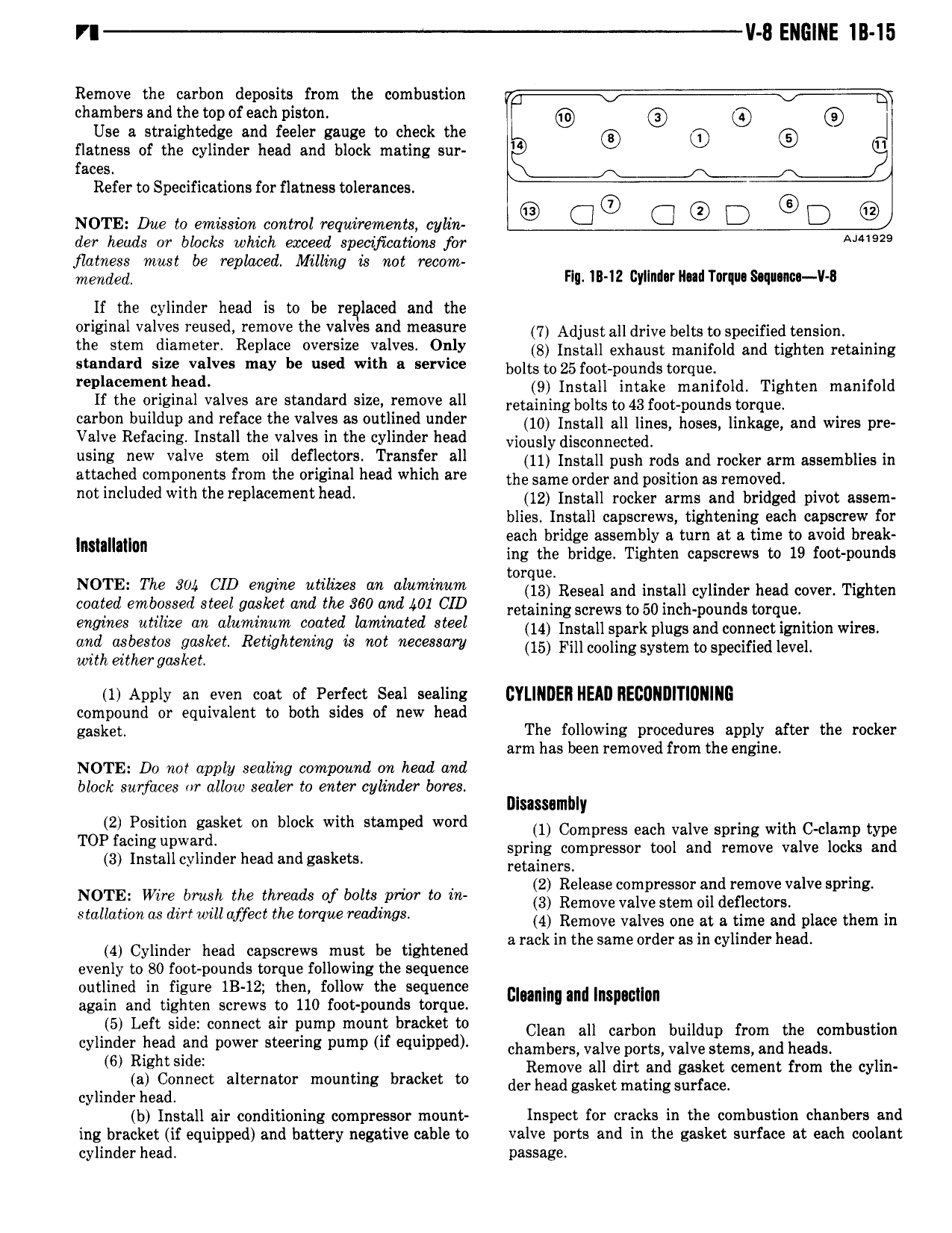
V ENGINE IB 15 Remove the carbon deposits from the combustion t chambers and the top of each piston 4 B Use a straightedge and feeler gauge to check the 0 O O l flatness of the cylinder head and block mating sur faces Refer to Specifications for flatness tolerances NOTE Due to emission control requirements cylin Cl Cl D D der heads or blocks which exceed specifications for 2 flatness must be replaced Mlling is not recom mmdm Flu IB I2 Gyllnlor Had Torquo 8 q onoo ll B If the cylinder head is to be replaced and the original valves reused remove the valves and measure 7 Adjust eil drive belts to specified teiieioit the Stem i emete Revleee everelee v lvee Oelv is Install exhaust manifold and tighten retaining statndard str vzlves may be used with a service bolts to25toot oodi ids toi dde P m 9 I t ll t k f ld T ht f ld If the original valves are standard size remove all rot inindltioilts tdlggggitlggiysidg toitdifg en mam 0 carbon buildup and reface the valves as outlined under 10 iootoii ali iioee hoeee linkage and wires pre Valve Refacing Install the valves in the cylinder head vioiisiy disoomiooted el e MW valve Stem ell lefleQt e Treneiee ell ii Install push indi and weren tin assemblies in attached components from the original head which are the some order and position eo removed et l le l v ththere le eme tl ee l iz tniten taken arms and tinged pivot assem blies Install capscrews tightening each capscrew for I t it ti each bridge assembly a turn at a time to avoid break on ing the bridge Tighten capscrews to 19 foot pounds 4 torque TfgissiyS g g yem i i 6 r ti leiz yrg iz Reseal inn install cylinder nan mei rignten retaining screws to 50 inch pounds torque More Melee ec elucmw coated lecmed Mel ii Install spark plugs and connect ignition Wim erilheetliteetve geielet Retiehtmc re ret ceeeeew in rm cooling iysttnitnspecitied ova wi ei ergos e 1 Apply an even coat ef Perfect Seal sealing CYLINDER NEAIJ IIECUNIIITIUNING compound or equivalent to both sides of new head gasket The following procedures apply after the rocker arm has been removed from the engine NOTE Do noi apply sealing compound on head and block surfaces or allow sealer to enter cylinder bores m M SISSBII1 Y Olzl Nosmon ggsket On muck mth Stamped Word 1 Compress each valve spring with C clamp type T Pfaimg iliw iF h d d k t spring compressor tool and remove valve locks and 3 nsta cy in er ea an gas e s retainers NOTE Wire bmsh the threads of bolts to in 2 Release compressor and remove valve spring 3 Remove valve stem oil deflectors Sm m dmmll qffect the www re d w8 4 Remove valves one at a time and place them in li 4 Cylinder head capscrews must be tightened arackin the sameorder asm cylinder ead evenly to 80 foot pounds torque following the sequence outlined in figure 1B 12 then follow the sequence again and tighten screws to 110 foot pounds torque man Ind Inslmmmn 5 Left Side n B t lm pump mwnt bracket m Clean all carbon buildup from the combustion ylind r heed fwd p w r steering pump if equlppedl chambers valve ports valve stems and heads 6 Rlght Sldei k Remove all dirt and gasket cement from the cylin cyHnde e onnect alternator mounting brac et to der head gggkgt mating gurfaogt b Install air conditioning compressor mount Inspect for cracks in the combustion chanbers and ing bracket if equipped and battery negative cable to valve ports and in the gasket surface at each coolant cylinder head passage

 Next
Next