Ford Parts Wiki | GM Parts Wiki
Home | Search | Browse | Marketplace | Messages | FAQ | Guest
|
Technical Service Manual January 1975 |
|
Prev

 Next
Next
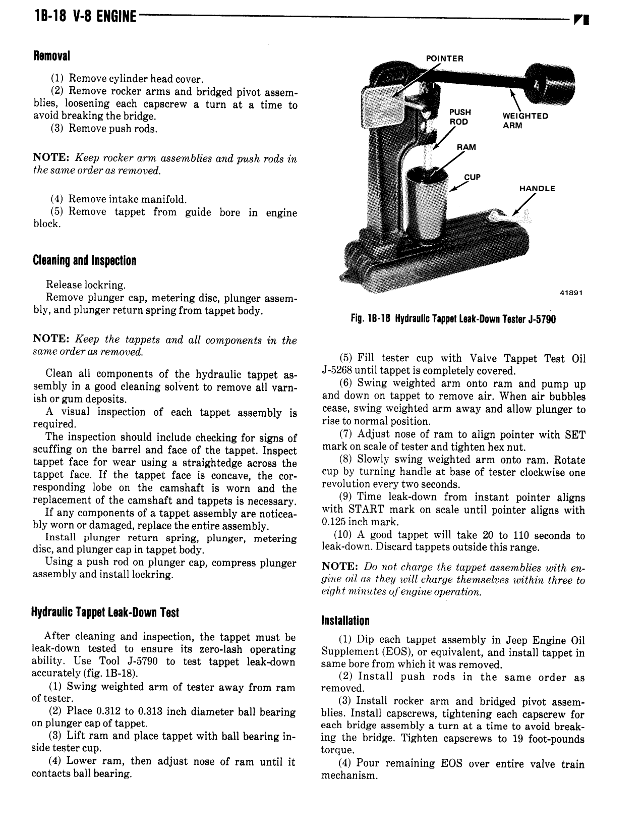
lll 18 ll 8 Elll lINE VI llllllllllll norman 1 Remove cylinder head cover V y 2 Remove rocker arms and bridged pivot assem blies loosening each capscrew a turn at a time to V PUSH avoid breaking the bridge V non xI HTED 3 Remove push rods V V RAM NOTE Keep rocker arm assemblies and push rods in thesameorderas removed V l V 0 4 Remove intake manifold Z 5 Remove tappet from guide bore in engine i block L Claanlnq and Inspacllon Release lockring Y 89 Remove plunger cap metering disc plunger assem bly d l l g l g l l b dy rn in in Ilydraullc nppu ual nm mm 1 mu NOTE Keep the tappets and all components in the Same l e d 5 Fill tester cup with Valve Tappet Test Oil Clean all components of the hydraulic tappet as J 52 usmlltappelliszmplewly i V red d ssmbly is s sm l l to rll vm a eLWl 2 i 35 E a l I at i t Sal Zgel0a of aa teapot aaaemay ia cease swing wslsltsd sm sw ml sllsw l s 0 required rise to normal position V V The inspection should include checking for signs of 7 Adlusf 5e of rsmto align pointer with SET scuffing on the barrel and face of the tappet Inspect mark on Scale of Ulster ang tighten hex nut tappet face for wear using a straightedge across the 8 Sl Wly Stlvlnglwelghted atlm mm ali R m tappet face ir the tappet face is concave the cor l by ly 6 bm Wm responding lobe on the camshaft is worn and the revulumll eve iw se r dS 1 replacement ofthe camshaft and mppaes is ecm y 9 Time ea down com instant pomfer alpha If any components of a tappet assembly are noticea with ZSTART mark on sca Q mm pointer a lgns Wit bly worn or damaged replace the entire assembly 0125 ucl mark Install plunger return spring plunger metering I 10 A coed lamvet will take 20 to 110 second to dism and plunger cap in mppet body eak down Discard tappets outside this range Using a push rod on plunger cap compress plunger NOTE Da not charge the topper assemblies with en msmblv l install l l rl s give on as new wuz charge themselves wana three to eight minules of engine operation Hydraulic Tappot La k D0vm Tas nm n After cleaning and inspection the tappet must be 1 Dip each tappet assembly in Jeep Engine Oil leak down tested to ensure its zero lash operating Supplement EOS or equivalent and install tappet in ability Use Tool J 5790 to test tappet leak down same bore from which it was removed accurately fig IB 18 2 Install push rods in the same order as 1 Swing weighted arm of tester away from ram removed of tester 3 Install rocker arm and bridged pivot assem 2 Place 0 312 to 0 313 inch diameter ball bearing blies Install capscrews tightening each capscrew for on plunger cap of tappet each bridge assembly a turn at a time to avoid break 3 Lift ram and place tappet with ball bearing in ing the bridge Tighten capscrews to 19 foot pounds side tester cup torque 4 Lower ram then adjust nose of ram until it 4 Pour remaining EOS over entire valve train contacts ball bearing mechanism

 Next
Next