Ford Parts Wiki | GM Parts Wiki
Home | Search | Browse | Marketplace | Messages | FAQ | Guest
|
Technical Service Manual January 1975 |
|
Prev

 Next
Next
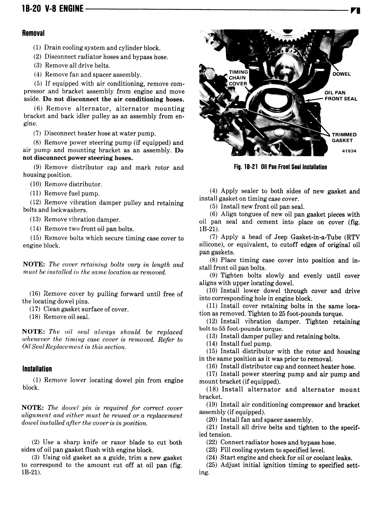
lll 20 v 8 EllGlllE r Removal je r 1 Drain cooling system and cylinder block ll lr lg V 2 Disconnect radiator hoses and bypass hose Q e Z 3 Remove all drive belts E In 4 Remove fan and spacer assembly gi gmmc e Q I Down 5 If equipped with air conditioning remove com COVER A pressor and bracket assembly from engine and move ge I OIL PAN aside Do not disconnect the air conditioning hoses Y Q l R l SEA 6 Remove alternator alternator mounting v X bracket and back idler pulley as an assembly from en n eine s 7 Disconnect heater hose atwater pump y TRIMMED 8 Remove power steering pump if equipped and X ll GASKET air pump and mounting bracket as an assembly Do 41934 not disconnect power steering hoses 9 Remove distributor cap and mark rotor and Fill HMI Ullpill F M l housing position 10 Removedistributor lm m V f rum ins il i Z1l iS ll c Zi c E fS f g l 12 Remove vibration damper pulley and retaining 5 Install new frost ell nan Senl whs and lmkwa hersj 6 Align tongues of new oil pan gasket pieces with 13 Remove vrbratwn d D Y oil pan seal and cement into place on cover fig 14 Remove two front oil pan bolts 1B 21 15 Remove bolts which secure timing case cover to nl APP V 3 bead of Jeep Gi ket ln a T be RTY engine block siliconen er equivalent to cutoff edges of original oil pan gas e s 8 Pl t t t d NOTE The cover retaining bolts vary in length and etal flensgg ngxgljts se cover m 0 pcs mn an In must be installed iii the same location as removed 9 Tighten belts slowly and evenly nntn eever aligns with upper locating dowel 16 Remove cover by pulling forward until free of 10 Inslaudiowiml ldllwel lhroglghkcover and drive enelomtlngdowelplns into correspon mg oemlengine ocl U Cl an ask L unece I V r 11 Install cover retaining bolts in the same loca g S 0 C0 B tion as removed Tighten to25 foot pounds torque 18 Remwe 1 S l 12 Install vibration damper Tighten retaining bolt to 55 foot pounds torque NOTE The ull wal always should be Wpllwed 13 Install damper pulley and retaining bolts whenever the timing ease cover is removed Refer to 14 Install fnelpump OllS2lllR plucelllelll lll lllls Seclwll 15 Install distributor with the rotor and housing in the same position as it was prior to removal lnemllnnn 16 Install distributor cap and connect heater hose 17 Install power steering pump and air pump and 1 Remove lower locating dowel pin from engine mount bi Mkgqii equipped blvck 18 Install alternator and alternator mount bracket NOTE The dowel pin is required for correct cover 85 5 ll li 23 lll0nlng compressor and bracket allgmllelll and gllllgr musl be freed F ll replace l 20 Install fan and spacer assembly do wel lllslulled llfler the wllellwlll pusllllm 21 Install all drive belts and tighten to the specif ied tension 2 Use a sharp knife or razor blade to cut both 22 Connect radiator hoses and bypass hose sides of oil pan gasket flush with engine block 23 Fill cooling system to specified level 3 Using old gasket as a guide trim a new gasket 24 Staff engine and check for oil UT coolant leaks to correspond to the amount cut off at oil pan fig 25 A li 5 1 1 l8l lgnlilvfl timing P 1f1 d Sett 1B 21 ins

 Next
Next