Ford Parts Wiki | GM Parts Wiki
Home | Search | Browse
|
Technical Service Manual January 1975 |
|
Prev

 Next
Next
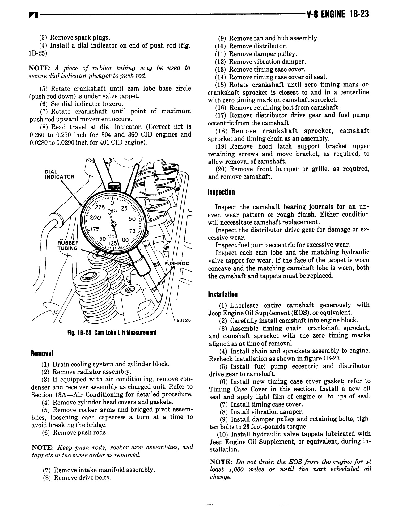
V II 8 ENGINE III Z3 3 Remove pg rk pIqcs 9 Remove mi and hub assembly 4 Install a dial indicator on end of push rod fig 10 Remove dieq ibue 0i lB 25 11 Remove damper pulley 12 Remove vibration damper NOTE A piece of rubber tulnng may be used to 13 Remove timingcuecoveh WC dm i d z l 7e to I h me 14 Remove timing case cover oil seal 5 netete crankshaft until ennn lobe base circle Ii hI e I sI I I we IFIIIIIK rI push md dowmis under Valve mppetn cran s aft sprocket is closest to and in a centerline 6 Set dial indium to uml with zero timing mark on camshaft sprocket 7 Rotate crankshaft until point of maximum ggxgxz r E 3ol l ir m i al el pump push rod upward movement occurs 8 Read travel at dial indicator Correct lift is gm from um camsmfh 0 260 to 0 270 inch inn 304 inn eee cm engines end spj c je n gg in 1 g jI j j agggxmti I f 0 0280 0 0290 hf 401 ID to mc or C engine 19 Remove hood latch support bracket upper Q retaining screws and move bracket as required to 2 i allow removal of camshaft 0 n V 20 Remove front bumper or grille as required INDICATOR and remove camshaft MM I lnspactlnn 225 O 35 i Inspect the camshaft bearing journals for an un Is s emo 50 even wear pattern or rough finish Either condition Q 4 will necessitate camshaft replacement I 5 75 p V Inspect the distributor drive gear for damage or ex iso 00 cessive wear 3 i v Q Inspect fuel pump eccentric for excessive wear 7 Inspect each cam lobe and the matching hydraulic UsHRLD valve tappet for wear If the face of the tappet is worn concave and the matching camshaft lobe is worn both 4 Q the camshaft and tappets must be replaced J i Installation 1 Lubricate entire camshaft generously with i Jeep Engine Oil Supplement EOS or equivalent 6 I26 2 Carefully install camshaft into engine block 3 Assemble timing chain crankshaft sprocket H In Z5 cm um un Mmumwn and camshaft sprocket with the zero timing marks aligned as at time of removal Nlmltllal R 14 gnsttzglfhain andhsprockegs asse b y to engine gg g jgj gj gg g gn j vII deI I I e EfiiiL Zeii i 12F nin 2 n C nnn iiieeiiinneen 3 If equipped with air conditioning remove con drlzzgiixstgaargiia kiug case cnver gasket refer to gender a Ar Y Ea WblY asfchalggecilugm Regr m Timing Case Cover in this section Install a new oil umm II on momng or em e prow ure seal and apply light film of engine oil to lips of seal 4 Remove cylinder head covers and gaskets 5 R k d b d 7 Install timingcaseoover I l Bmqve mc Er arms en N Std PWM S m 8 Install vibration damper gxjx b h rid ps rew 8 tum at 3 time U 9 Install damper pulley and retaining bolts tigh ten bolts to 23 foot pounds torque 6 Rem v push r dS 10 Install hydraulic valve tappets lubricated with NOTE Keep push rads rocker arm assemblies and gsgsatizglne Ou Supp amen or equwa ent urmg In tappets in the same orderas removed NOTE Da not drain the EOS from the enpine for at 7 Remove intake manifold assembly kast 1 000 mike or until the next scheduled oil 8 Remove drive belts change

 Next
Next