Ford Parts Wiki | GM Parts Wiki
Home | Search | Browse
|
Technical Service Manual January 1975 |
|
Prev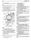
 Next
Next
IB 24 V 8 ENGINE VI 11 Install intake manifold assembly 4 Apply engine oil to oil pan contacting surface 12 Install push rods of front and rear oil pan seals 13 Install rocker arms and bridged pivot assem 5 Install oil pan and tighten drain plugsecurely blies Install capscrews tightening each caps screw for each bridge assembly a turn at a time to avoid break NOTE Tighten 1 L 20 oil pan screws to 7 o0t p0unds ing the bridge Tighten capscrews to 19 foot pounds torque and 5 16 18 oil pan screws totfoot pounds tor torque que 14 Install cylinder head covers and gaskets 15 Install fuel pump 6 Install starter 16 Rotate crankshaft until No 1 piston is at TDC 7 Fill crankcase to specified level with new oil position on compression stroke NOTE After No 1 intake valve not closed mc mi O F TE be reached by rotating the crankshaft clockwise as viewed from the front until the timing mark or the h Ad n2 wc ll miie Igggzlgggsigle t2 r v T0 i damper aligns with TDC on the timing case cover csgssiil E 0 0 mgm A bypass valve incorporated in the filter mounting NJ1i tii iT l idL Zil E12SCLiil S r ii SLZtZlig diiZLiiY me Provide e sfev facie in the mt the film becomes inoperative as a result of dirt or sluge accu 18 Install distributor cap mulation Oil Filter Remover Tool J 22700 will facil1 19 Install ignition wires tate removal 20 If removed install air conditioning condenser Before installation apply a thin mm of Dil to the and receiver assembly Refer to Section 13A A1r Con mt k t D0 not u B ea Install filter until ditioning for procedure to purge compressor air asiiitgiini cts the Se Ogrthgzdapwr Tighten by hand only following instructions on replacement fil gigggfniggijiigrgy ggi be cpm before ter Operate engine at fast idle and check for leaks 21 Install hood latch support bracket retaining ml PUMP screws and tighten securely 22 If removed install front bumper or grille A positive displacement gear type oil pump is used 23 Install radiator and is driven by the distributor shaft which in turn is 24 Fillcooline System to P lfl dl V l driven by a gear on the camshaft fig 1B 4 The pump which is part of the timing chain cover incor ml Pm porates a pressure relief valve to regulate maximum pressure Crankcase oil enters the pump after being drawn NIIIIIIWI through the pickup tube and screen assembly the 1 Drain Engine Oi hogkzoigtal matt oil gallery and the connecting passage in e immgc ain cover Eemuve Sianen Oil pump removal or replacement will not affect me lpa d b t t th d trib t dri ea 4 Remove oil pan front and rear neoprene oil Nui u r Im as B is u or ve g r seals Thoroughly clean the gasket surfaces of oil pan mmams m mesh with the c3 mShaftgear and engine block Remove all sludge and dirt from oil pan sump Oli PNSSIIN NINIBI Vlllll The oil pressure relief valve is not adjustable A Insmmmn setting of 75 pounds maximum pressure is built into the tension of the spring 1 Install the oil pan front seal to timing we iii the relieved position the valve permits oil to by WVBF and PPlY 3 E 0 8m i tif Jeep G Sk t l pass through a passage in the pump cover to the inlet a Tube RTV silicone or equivalent to end tabs gidg of the pump 2 Cement new oil pan side gaskets into position on engine block and apply a generous amount of Jeep R I Gasket in a Tube RTV silicone or equivalent to side www gasket contacting surface of seal end tabs 1 Remove retaining screws and separate the oil 3 Install seal in the recess of rear main bearing pump cover gasket and oil filter as an assembly from cap making certain it is fully seated pump body timing cover