Ford Parts Wiki | GM Parts Wiki
Home | Search | Browse
|
Technical Service Manual January 1975 |
|
Prev
 Next
Next
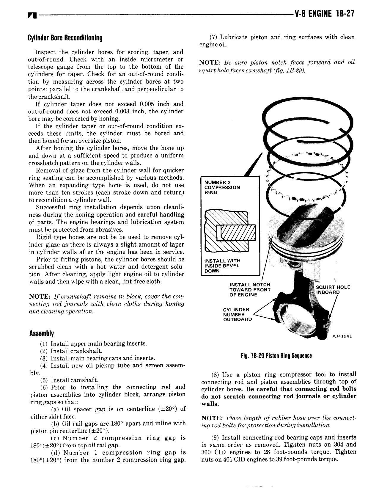
r V ll ENGINE lll 27 cylindgr Burg Rpggndiligninll 7 Iolibricate piston and ring surfaces with clean engine o1 Inspect the cylinder bores for scoring taper and out of round Check with an inside micrometer or d telescope gauge from the top to the bottom of the lfzfffztgghlgaggg forward an my cylinders for taper Check for an out of round condi tion by measuring across the cylinder bores at two points parallel to the crankshaft and perpendicular to the crankshaft If cylinder taper does not exceed 0 005 inch and out of round does not exceed 0 003 inch the cylinder bore may be corrected by honing If the cylinder taper or out of round condition ex ceeds these limits the cylinder must be bored and then honed for an oversize piston After honing the cylinder bores move the hone up and down at a sufficient speed to produce a uniform crosshatch pattern on the cylinder walls Removal of glaze from the cylinder wall for quicker or ring seating can be accomplished by various methods jk When an expanding type hone is used do not use ggm s ON more than ten strokes each stroke down and return R NG Mol f to recondition a cylinder wall l r Successful ring installation depends upon cleanli ness during the honing operation and careful handling of parts The engine bearings and lubrication system l must be protected from abrasives i I Rigid type hones are not be be used to remove cyl 1 inder glaze as there is always a slight amount of taper j W in cylinder walls after the engine has been in service Prior to fitting pistons the cylinder bores should be lng ALL wu H lg scrubbed clean with a hot water and detergent solu sgml BEVE tion After cleaning apply light engine oil to cylinder walls and then v ipe with a clean lint free cloth lpgvlg h gags 3UmT HOLE 1 sono NOTE If crankshaft remains in block cover the con DF ENGWE nesting rod journals with clean cloths during honing o nd cleaning operation l J g R ouraoanu V A lv 4 1 Install upper main bearing inserts 2 Install crankshaft 3 Install main bearing caps and inserts HW lam FISH 1 4 Install new oil pickup tube and screen assem bll 48 Use a piston ring compressor tool to install l5l I tall lsh connecting rod and piston assemblies through top of 6 PHO W lllstalhng the tmg md and cylinder bores Be careful that connecting rod bolts piston assemblies into cylinder block arrange piston do not scmwh cmmectlng md journals 0 cylinder ringgalzsso llal V t I4 200 f wallS a 1 spacer gap 1s on cen er 1ne o either Skirt face NOTE Place length of rubber hose over the connect b Oil rail caps are 180 avm ami l WM no ood bolts foo protection durlngirwlallalwn PISIOH pm centerl1ne 20 c Number 2 compression ring gap is 9 Install connecting rod bearing caps and inserts 180 20 from top oil railgap in same order as removed Tighten nuts on 304 and d Number I compression ring gap is 360 CID engines to 28 foot pounds torque Tighten 180 d 20 from the number 2 compression ring gap nuts on 401 CID engines to39 foot pounds torque