Ford Parts Wiki | GM Parts Wiki
Home | Search | Browse
|
Technical Service Manual January 1975 |
|
Prev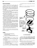
 Next
Next
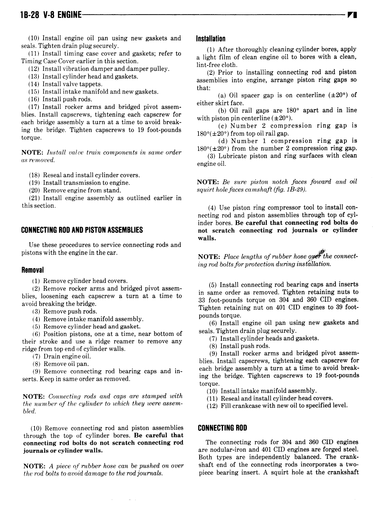
1ll 28 V 8 EllG llE VI 10 Installdengine oil pan using new gaskets and 5 3 3 i r seals Tighten rain plugsecurely 1 After thoroughly cleaning cylinder bores apply dll Install timing gas cm gr aml gaskem refer to a light film of clean engine oil to bores with al clean Timing Case Cover earlier in this section umrfree cloth xlffsgginhiggngsgZggkiiglper pulley 2 Prior to installing connecting rod and piston blies into engine arrange piston ring gaps so 14 Install valve tappets ASSET 15 Installintake manifold and new gaskets thai 3 Oil Spacer gap is on centerline 20 of 16 Install push rods either skirt face 17 Install rocker arms andkbridged pivot assem b Oil mil gaps are 180 apart and in line blies Install capscrews tightening each capscrew for with piston pm centerl1ne t20 each bridge assembly a turn at a time to avoid break 0 Number 2 com ression ring gap is ing the bridge Tighten capscrews to 19 foot pounds 180 t20 fr0m mp Oilrailgag 0 que d Number 1 compression ring gap is 180 20 from the number 2 compression ring gap j7 l g Wm r 1 1 3 Lubrieate e e e en eng with clean engine oil 18 Reseal and install cylinder covers 19 Install transmission to engine NOTE Be sure piston notch faces foward and oil 20 Remove engine from stand squirt hole faces camshaft Gig 1B 29 21 Install engine assembly as outlined earlier in mls s U 4 Use piston ring compressor tool to install con necting rod and piston assemblies through top of cyl inder bores Be careful that connecting rod bolts do UUNNECTING llllll IND Plsllllll ASSEMBUES not scratch connecting rod journals or cylinder walls Use these procedures to service connecting rods and pistons with the engine m the can NOTE Place lengths of rubber hose o he connect ing rod bolts for protec tion during instdlhztiovt Removal 1 Remove cylinder head covers 2 Remove eeeieee arms eee bridged pivot assem 5 md P 2 5 9 in same order as removed Tighten retaining nuts to blues loosening each capscrew a turn at a time to 33 foot pounds torque on 304 and 360 CID engines avogxlggllxggetgxsirciii Tighten retaining nut on 401 CID engines to 39 foot pounds torque ggzgx eT 2 g0 13S T i 6 Install engine oil pan using new gaskets and 6 Position pistons one at a time near bottom of sBalS T ght drivndplug Segurelgh k ts their stroke and use a ridge reamer to remove any Insglm rzjisea San gas e cl s 1 1 1 1 ll S N r r aEgpB in m Er Wa S 9 Install rocker arms and bridged pivot assem 8 Remove on pan blies Install capscrews tightening each capscrew for 9 Remove connecting rod bearing caps and in Qchtllsriiggdassealgmjntggsiiezgnx t l pl r serts Keep in same order as removed ml B ri ge 1 torque 10 Install intake manifold assembly NOTE Connectmy rods and caps ore stamped with 11 Resealandinstallcylinder headcuveli d b vf the Vl d t which they wwe MSW 12 Fill crankcase with new oil to specified level e 10 Remove connecting rod and piston assemblies BDNIIEUTING MI through the top of cylinder bores Be careful that connecting rod bolts do not scratch connecting rod The connecting rods for 304 and 360 CID engines journals or cylinder walls are nodular iron and 401 CID engines are forged steel Both types are independently balanced The crank NOTE A piece qfrubber hose can be pushed mt over shaft end of the connecting rods incorporates a two the rod bolts to avoid damage to the rod j0ru1 ru1La piece bearing insert A squirt hole at the crankshaft