Ford Parts Wiki | GM Parts Wiki
Home | Search | Browse
|
Technical Service Manual January 1975 |
|
Prev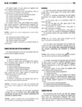
 Next
Next
85510
r ENGINE IB 29 Connecting llod llaarlng Fitting Chart Cmksllll Connnctlnq lint Journal liurinn Color Bod Bnlur me ind nlnnmr ln lama limrnnr sin uppnr lnwt size Lrwm tnxm sln 304 M lilll Ennins Yellow 2 0955 to 2 0948 Standard Yellow Standard Yellow Standard Orange 2 0948lo 2 0941 0 0007 Underslze Yellow Standard Black 001 lnch Undersize Black 2 0941 to 2 0934 0 0014 Underslze Black 001 Irion undersize Black 001 lncrr undersize Red 2 085510 2 0848 0 010 Undersizc Red 010 lnclr Undersiza Red 010 inch undersize 401 Glll Enqint Yellow 2 24B5to2 2470 Starrdardl Yellow Standard Yellow Standard orange 2 247oto 2 2471 0 0007 undersize Yellow standard Blank 001 lnon undersize Black 2 2471io 2 2464 0 0014 Underslzel Black 001 inch Undersiza Black 001 inch Undersrze Red 2 2305 to 2 2378 0 010 Undersize Red 010 men Undersize Red 010 inch Underslze 60270 end provides lubrication for the cylinder walls Example pistons and piston pins If must face inward when the Conool lnoorroo connecting rod is installed fig IB 29 The removable Upper Standard Standard bearing cap has a number from 1 through 8 stamped LOWQPO 001 inCh 0002 in h on it and the adjacent machined surface of the rod to undersiz C identify the cylinder in which the rod was assembled The piston end of the d is 3 2000 P und PT S flt tv Service replacement hearing inserts are available the Plswn Pin in pairs in the following sizes standard 0 001 inch un H the n 8 rod l znm l k d by 3 dersize 0 002 inch undersize 0 010 inch undersize and competent machine shop Wn n V engine wear DBF 0 012 inch undersize The size is stamped on the back terns or damage indicates probable rod misalignment of the Service replacement inseyga Always replace bent connecting rods NOTE The 0 002 and 0 012 inch undersize inserts din production connecting llod ltuarmqs are me The connecting rod bearings for all V 8 engines are mmovol steel backed aluminum alloy precision type The Fonneclinll md bearings are Select fit to their Use this procedure to service connecting rod bearing respective journals to obtain the desired operating with the onglno ln the Vehlolol clearance In production the select fit is obtained by using various sized color coded bearing inserts as lll Drarp Bnglne n shown in the bearing fitting chart The bearing color 2 Remove oil pan me appears me the edge l the r Bmpz me on noaa crankshaft as required to position wa not stamped on inserts used in production looting rod journal at bottom of Stroko The rod journal size is identified in production by a 4 Romovo bearing oops and lower insergg we md pm mark Op the edrmpt cheek or to remove upper me by rotating insert out of counterweight toward the flanged rear end of the connecting md crankshaft Use color codes shown in the bearing Gtt ing chart to identify journal size and select the correct bearing inserts to obtain proper clearances NOTE Do not mix bearing caps Each connecting When required different sized upper and lower rod gud matchmgh Fa lju p t U e tii hgfzi bearing inserts may be used as a pair therefore a Zml eign afmgfeme block The numbers me standard size insert is sometimes used in combination LC ji e O hgmzmiurfmau Mite the 8 MN with a 0 001 inch undersize insert to reduce clearance fc em m Ba3 mc rr pp q by 0 0005 inchll Zthousandth of an inch O 8 g CAUTION Newer use bearing inserts with greater 6 Inspect bearing inserts and replace if worn or than I 001 inch dzfference in size in pairs damaged