Ford Parts Wiki | GM Parts Wiki
Home | Search | Browse
|
Technical Service Manual January 1975 |
|
Prev
 Next
Next
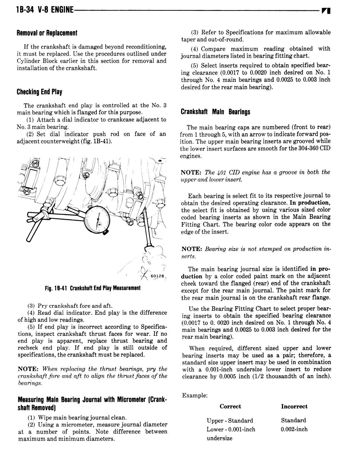
IB 34 V 8 ENGINE r RIIIIIIVII 0I IMIIIIFGIIOIIY 3 Refer to Specifications for maximum allowable taper and out of round If the crankshaft is damaged beyond reconditioning 4 Compare maximum reading obtained with it iust be r pia ed US h pr i r S utli d mdu journal diameters listed in bearing fitting chart Cylinder Block earlier in this section for removal and lnslallatlon of the crankshaft 5 Select inserts required to obtain specified bear ing clearance 0 0017 to 0 0020 inch desired on No 1 through No 4 main bearings and 0 0025 to 0 003 inch d d f th b in cmcklnl End may esire or e rear main ear g The crankshaft end play is controlled at the No 3 main bearing which is flanged for this purpose CNIIKSIIIH Mlill B0 l iII 8 1 Attach a dial indicator to crankcase adjacent to N0 3 main bearing The main bearing caps are numbered front to rear 2 Set dial indicator D 1Sh Wd 011 806 of M1 from lthrough 5 with an arrow to indicate forward pos adjacent 0 1 W igh fig lB 4l ition The upper main bearing inserts are grooved while the lower insert surfaces are smooth for the 304 360 CID i l f l r M l W englm Q ill Y l NOTE The 401 CID engine has a groove in both the ij ii Gi i Q4 rk upper and lowerinrm AA 9 i F o i e V Yi l Each bearing is select fit to its respective journal to K l obtain the desired operating clearance In production 4 i N l the select fit is obtained by using various sized color il l coded bearing inserts as shown in the Main Bearing Q O Fitting Chart The bearing color code appears on the i edge of the insert Fl NOTE Bearing size is not stamped xm production in 1 serts xx H J The main bearing journal size is identified in pro 232 duction by a color coded paint mark on the adjacent h kt dthn d dfth kshatt F M v 2 2 5 irilaire Qtr l 2 l E lf r pailirriirk rm the rear main journal is on the crankshaft rear flange 3 Pry crankshaft fore and aft Use the Benin g Fitting Chart to select proper bear lh 4 lR l g 1 f End may me d ff ng to their at specified bearing clearance 0 Eg 31 gw lea ingl rr t rdin to S Rifles 0 0017 to 0 0020 inch desired on No 1 through No 4 en p ey is ec g P main bearings and 0 0025 to 0 003 inch desired for the tions inspect crankshaft thrust faces for wear If no mar main bearing end play is apparent replace thrust bearing and Fechefk end Play If end PNY is still outside of When required different sized upper and lower specifications the crankshaft must be replaced bearing inserts may be used ag E pair therefore s standard size upper insert may be used in combination NOTE Whw Wpllwiw the h u8 b I7 l7L98 PU the with a 0 001 inch undersize lower insert to reduce T k h f f0 and aff tv illitm me ih7 u8 668 of the clearance by 0 0005 inch 1 2 thousandth of an inch eormgs E l Musurlng Maln Bunny Joumal wltn Nllcromalar Crank Kamp smh mmayndl Correct Incorrect 1 Wipe mainlbearing journal clean l Upper Standard Standard 2 Using a micrometer measure journal diameter h at a number of points Note difference between L 00l i 0 0 2 maximum and minimum diameters undersize