Ford Parts Wiki | GM Parts Wiki
Home | Search | Browse
|
Technical Service Manual January 1975 |
|
Prev
 Next
Next
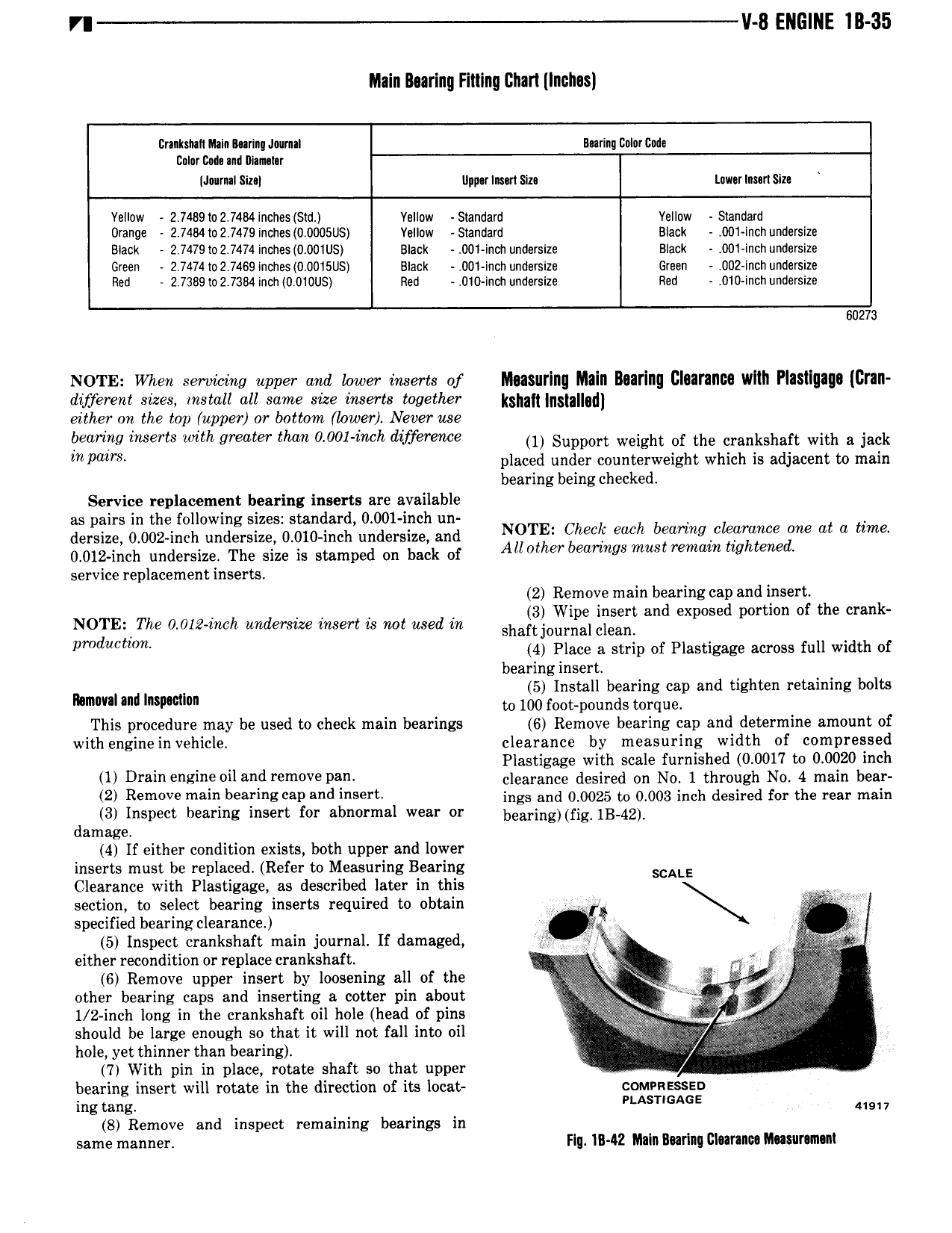
8 ENGINE IB 35 Maln llearlnn Fitting Chart Inches ltmksrnll Main Marin Jnumal Bearing Bnlnr we nnler me rnd nununr JurmlSiz l llpwlnen me inwerlmn Size Yellow 2 7489 i02 7484 incnes sn1 Yellow Slandaru vellew Standard Orange 2 7484le2 7479ln ies 0 0U05US Valluw S1andard Black 001 lnchum1erslze Black 2 7479io 2 7474 lnones 0 001Lls slack 00i indi undersize Black 001 incn unaerslze Green 2 7474 i02 7469 lnones 0 0U15US Black 00l inch undsrsrze Green 002 Inch undersize Rec 2 738s to 2 7384 indi 0 010US neu 010 inch unoersize neu 010 inch unuerslze 60273 NOTE when servicing upper and lower inserts of Measuring Maln Bearing Clearance wltli Plasligage Gran diyerent sizes install all same size inserts together k g g gd either on the top upper or bottom lower Never use oeimng inserts with greater than 0 001 mch difference 1 Support weight of the crankshaft with a jack p 8 placed under counterweight which is adjacent to main bearing being checked Service replacement bearing inserts are available as pairs in the following sizes standard 0 001 inch un emits 0 002 rmh underside 0 010 ncn enemies and NOTE Glen ml l W l eW m me at a time 0 012 inch undersize The size is stamped on back of Allmher bemwgs mm remain twhwned service replacement inserts 2 Remove main bearing cap and insert NOTE The 0 012 inch undersize insert is not used in sha gogfsl 3 and exposed pm mm of the crank pmducmm 4 Place a strip of Plastigage across full width of bearing insert 5 Install bearing cap and tighten retaining bolts Mmm um Immun to 100 foot pounds torque This procedure may be used to check main bearings 6 Remove bearing cap and determine amount of with engine in vehicle clearance by measuring width of compressed Plastigage with scale furnished 0 0017 to 0 0020 inch lll Drain engine 0 1 and remove Dana clearance desired on N0 1 through No 4 main bear 2 Remove m i l i s l Md i rt4 ings and 0 0025 to 0 003 inch desired for the rear man 3 Inspect hearing insert for abnormal wear or bearing fig 1B 4g damage 4 If either condition exists both upper and lower inserts must be replaced Refer to Measuring Bearing SCALE Clearance with Plastigage as described later in this section to select bearing inserts required to obtain t f specified bearing clearance N 1 y V M 5 Inspect crankshaft main journal If damaged 5 V either recondition or replace crankshaft i if 6 Remove upper insert by loosening all of the 5 r i other bearing caps and inserting a cotter pin about I 1 2 inch long in the crankshaft oil hole head of pins Q 1 g should be large enough so that it will not fall into oil X i hole yet thinner than bearing 7 With pin in place rotate shaft so that upper bearing insert will rotate in the direction of its locat comenzssen ing tang AsT A E usr 7 8 Remove and inspect remaining bearings in same manner Fig lll 42 Main Bearing Clearance MISIITIIIIII