Ford Parts Wiki | GM Parts Wiki
Home | Search | Browse
|
Technical Service Manual January 1975 |
|
Prev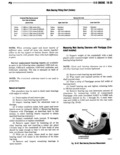
 Next
Next
IB 36 V 8 EIlG NE r lI lilllll I 3 Apply heat to expand inside diameter of 1 Lubricate bearing surface of each insert with replacement nggean clean engine Oil 4 Press replacement ring gear onto flywheel 2 Loosen all main bearing caps 3 Install main bearing upper insert s On he h l 4 Install main bearing i ap s and lower insems NOTE Wwllgdd rlglwnzlsswn t d jlgw ee ts Tighten retaining bolts evenly to 100 foot pounds tor balagwed Gif W WL wglcogpanem lm at G pal que in steps of 30 60 90 and 100 foot pounds mr que Of 2 Wifi Sl iff llils irlbyi 0 nat attain o up increments turning crankshaft at each step to deter Fam g miw S W sn msu mine if crank rotates freely If crank does not rotate ngasuvlce mp m m freely check inserts for proper installation and size 5 After installation turn crankshaft to check for SIIUIIT zlllilllla ASSEMBLY 6 Install oil pan using new gaskets and seals Tighten drain plug securely 7 Fill crankcase to specified level with new oil Servlce replacement Sh t lmglne aS mblY may be installed whenever the original engine block IB damaged beyond repair The short engine assembly FLYWREEL ARI STARTER RIRG GEAR ASSEIAILY consists of sn glne block piston and rod assemblies khft hft l Ittb d t The mm me gw can be replaced v l ZZ Lsel d SITE lri le Zr i uli EEZ r SEI with manual transmission only The starter ring gear assen bly always install a new Engine Oil pump pickup is welded to and balanced as part of the converter tube and screen assembly drive plate on vehicles with automatic transmission lling GsarRaplacamanl ManuaITnnsilllsslan NOTE Short engine assemblies rrrelnele rr repznee 1 Place flywheel on an arbor press with steel gxzihcffgzieiibi iltig ifig lgigricizz rexlgvigfw and blocks equally spaced under gear 2 Press flywheel through ring gear Transfer component parts from the original engine NOTE The ring gear can also be removed by break following procedures and clean and tighten as ing il with a chisel required ll 8 Enqlnu Slmllllsalluns Bore Compression Ratio Continued 304 3 75 inches 8 25 360 4 08 inches 401 1 401 4 165 inches ccmprsssicn Pressure Stroke 304 140 psi min 304 3 44 inches 360 2V or 4V 140 psi min 360 3 44 inches 401 140 psi min 401 3 68 inches Maximum Variation Between Cylinders 20 psi min T i ilY i i i il i 45 cc 304 304 cu inches 360 360 cu inches ig 401 401 cu inches Compression serie Camshaft 304 8 40 1 Fuel Pump Eccenrric Diameter 2 182 inch lc 2 192 inch 360 2V or 4V 8 25 1 Tapper Clearance Zcrc lash hydraulic rappers scams