Ford Parts Wiki | GM Parts Wiki
Home | Search | Browse
|
Technical Service Manual January 1975 |
|
Prev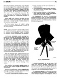
 Next
Next
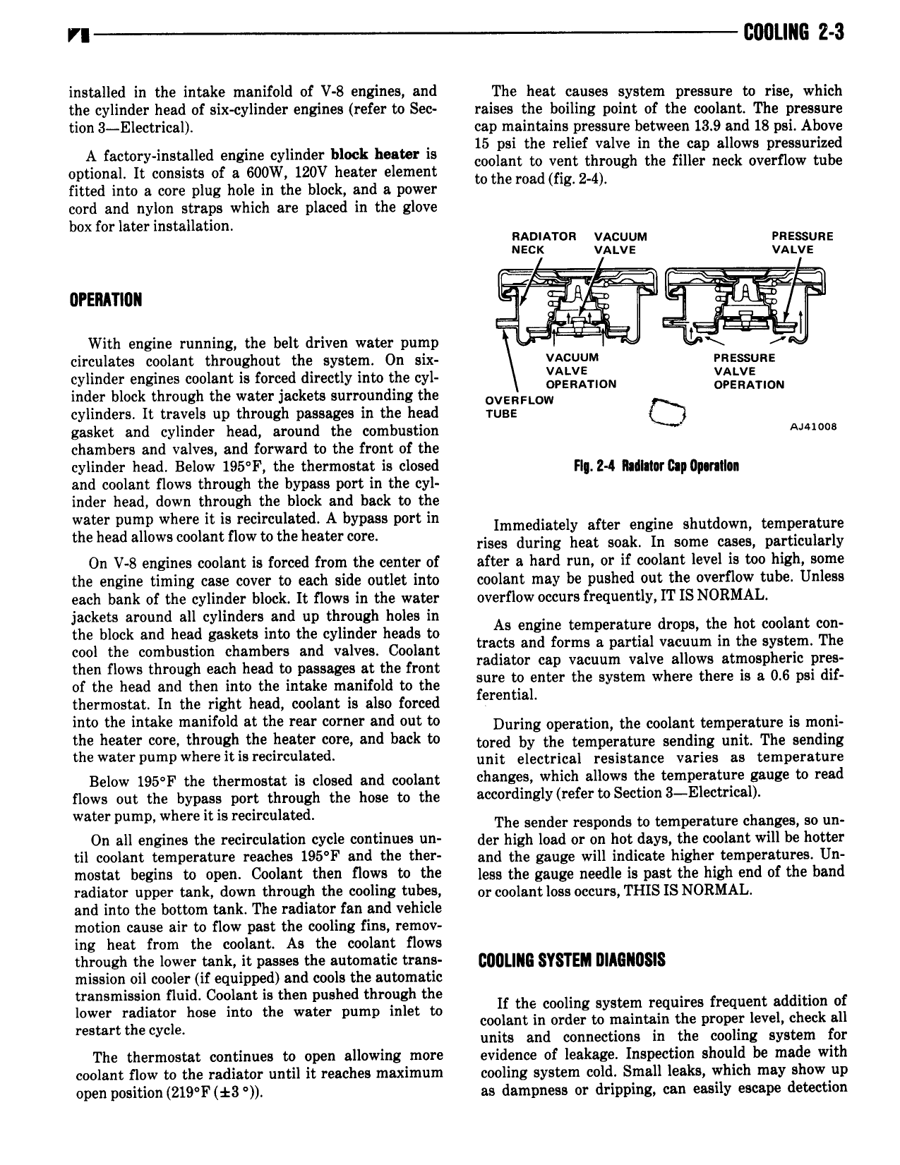
VI 2 l0L IlG Z 3 installed in the intake manifold of V 8 engines and The heat causes system pressure to rise which the cylinder head of six cylinder engines refer to Sec raises the boiling point of the coolant The pressure tion 3 Electrical cap maintains pressure between 13 9 and 18 psi Above 15 psi the relief valve in the cap allows pressurized 4 e y d eeelsht th Veht through the filler heck hvehhhw thhe optional It consists of a 600W 120V heater element to the madmg 24 fitted into a core plug hole in the block and a power cord and nylon straps which are placed in the glove box for later installation naomron vacuum ensssuaz neck vahve vahve orsnmou ar T hi U 1 4l K l rr E 1 With engine running the belt driven water pump l circulates coolant throughout the system On six xiwgtc I i 2 IRE cylinder engines coolant is forced directly into the cyl OPERATION OPERATION inder block through the water Jackets surrounding the OVERFLOW cylinders It travels up through passages in the head ruse Q gasket and cylinder head around the combustion A chambers and valves and forward to the front of the cylinder head Below 195 F the thermostat is closed Fl 2 4 hll 1crB p0p nl and coolant flows through the bypass port in the cyl inder head down through the block and back to the hZ 2 l ll 5 55 2i h 2 f s 2e Z h s 3 3 q g gt 8 S g t 5 g On V 8 engines coolant is forced from the center of after a hard run or if coolant level is too high some the engine timing case cover to each side outlet into coolant may be pushed out the overflow tube Unless each bank of the cylinder block It flows in the water overflow occurs frequently IT IS NORMAL jackets around all cylinders and up through holes in the block sha head gaskets into the Cyllnd f heads to A g F d p l cool the combustion chambers and valves Coolant tm ts and fame 8 pamal Vacuum m the systlm The then flows through each head to passages at the front mdmmr up vacuum Valve aww mll sph Pix of the head aha theh thm the ihtahe mahuem to the 4 W thermostat In the right head coolant is also forced t Bl into the intake manifold at the rear corner and out to During Operation the coolant temperature is mont the healer thm h the heater md Mk W tored by the temperature sending unit The sending me Water Wm when his recircuhted unit electrical resistance varies as temperature Below 195 F the thermostat is closed and coolant h E S which ll W the mP EWS 0 mad news out the bypass port through the hose to the cc rdinz1y referwS ti0n 3 E1 ri 1 ww me it is mi e The sehheh hahaha e ehpehsthhe changes sh On all engines the recirculation cycle continues un day high load or on hot days the coolant will be hotter til coolant temperature reaches 195 F and the ther and the gauge will indicate higher temperature Uh m b Ei to 0D Coolant than fl W W the less the gauge needle is past the high end of the band radiator upper tank down through the cooling tubes 0 cgolgntlggg Occurs THIS IS NORMAL and into the bottom tank The radiator fan and vehicle motion cause air to flow past the cooling fins remov ing heat from the coolant As the coolant flows through the lower tank it passes the automatic trans 0 SYSTEM Q mission oil cooler if equipped and cools the automatic im E sE0 t 5 h Ial h En r ttl If the cooling system requires frequent addition of restart the cycli coolant in order to maintain the proper level check all units and connections in the cooling system for The thermostat continues to open allowing more evidence of leakage Inspection should be made with coolant flow to the radiator until it reaches maximum cooling system cold Small leaks which may show up open position 219 F t3 as darnpness or dripping can easily escape detection