Ford Parts Wiki | GM Parts Wiki
Home | Search | Browse | Marketplace | Messages | FAQ | Guest
|
Technical Service Manual January 1975 |
|
Prev
 Next
Next
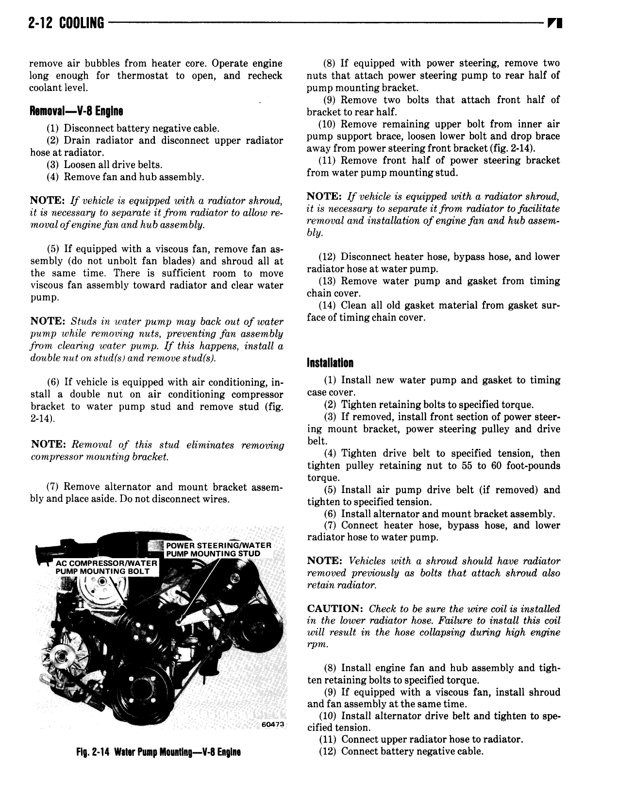
2 12 EIIULIIIG VI remove air bubbles from heater core Operate engine 8 lf equipped with power steering remove two long enough for thermostat to open and recheck nuts that attach power steering pump to rear half of coolant level pump mounting bracket 9 Remove two bolts that attach front half of llunnval ll 8 Enqlm bracket to rear half 1 Disccnncct battery ncgativc c8blc 10 Removebremaamng upper lie fro ndinner air 2 Drain radiator and disconnect upper radiator pump suppmlt m S w r t all mp brew hose at mdiatcc away from power steering front bracket fig 2 14 3 Lccsen alldrivc bclcsc 11 Remove front half of power steering bracket 4 Remove fan and hub assembly mm Water pump mmlmng stud NOTE If tenure is equipped with a mum shroud l TE If l eq iPP d i 7 l l it is necessary to separate it from radiator to allow re it is eS l to Sephmte li f V Tadlatw t fammate mow Ofmginefan and hub assembly xmoval and installation of engine fan and hub assem y 5 lf equipped with a viscous fan remove fan as sembly do not unbolt fan blades and shroud all at 2 D S n t heater h s bypass h s and lower the same time There is sufficient room to move re mw me At water pump f viscous fan assembly toward radiator and clear water hllal R V water pump and gasket mm mm pump c ain cover l 14 Clean all old gasket material from gasket sur NOTE Studs in water pump may back out of water face f umm cha v r pump while removing nuts preventing fan assembly from clearing water pump lf this happens install a double nut on stud s and remove stud s Incmmlcl 6 If vehicle is equipped with air conditioning in ll Inswll new Water Dump and B8 k t to timlnl stall a double nut on air conditioning compressor case V9 bracket to water pump stud and remove stud fig 2 T EhW l l l 8b lt W D lf d i l Q 2 14 3 If removed install front section of power steer ing mount bracket power steering pulley and drive NOTE R l lh t d l t b l c0mpTesS0 T L g l ti b k u mmm ex Temwmg 4 Tighten drive belt to specified tension then tighten pulley retaining nut to 55 to 60 foot pounds torque 7 Removealternator and mount bracket assem 5 nam ai pump drive belt ig removed ddd bly and place aside Do not disconnect wires tighten to specified wnSi0n 6 Install alternator and mount bracket assembly 7 Connect heater hose bypass hose and lower d to h to t kc rowsnsrssnnrzo wagzn ra Ia r OSB Wa Er pump vumv Mounrm u Ac c0MpRE g R wArER J NOTE Vehicles with a shroud should have radiator PUMP M UNT NG BDU e removed previously as bolts that attach shroud also 1 a retain radiator s L Qs i 3 42 CAUTION Check to be sure the uvire coil is installed i 7 Y in the hzwer radiator hose Failure to install this coil V Q will result in the hose collapsing during hihh engine in s i l rpm c 5 S Install engine fan and hub assembly and tigh Qjl QQ ten retaining bolts to specified torque V c Y 9 If equipped with a viscous fan install shroud and fan assembly at the same time 10 Install alternator drive belt and tighten to spe W cified tension 11 Connect upper radiator hose to radiator FI 2 14 Umar Puqp Inmlng V Eqglqs 12 Connect battery negative cable