Ford Parts Wiki | GM Parts Wiki
Home | Search | Browse
|
Technical Service Manual January 1975 |
|
Prev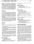
 Next
Next
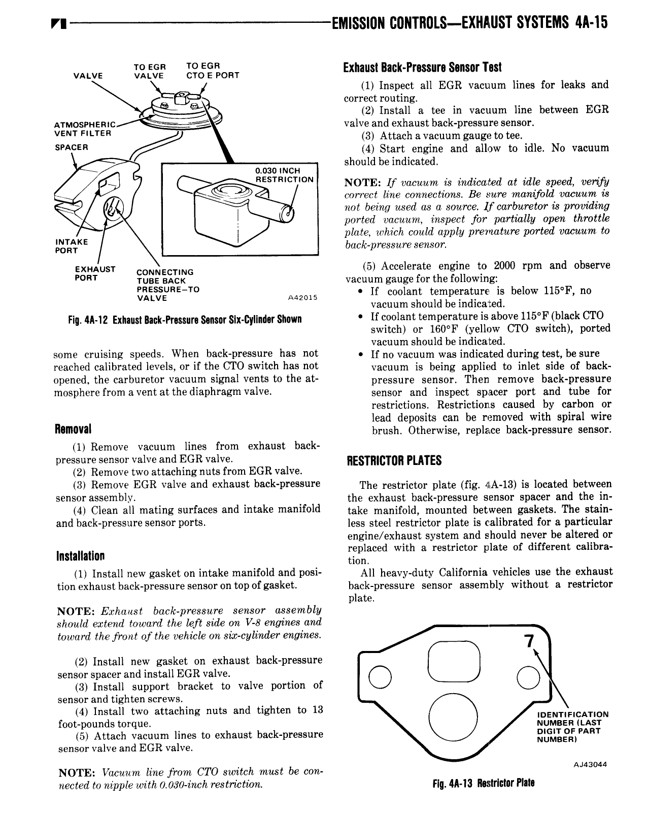
V Ell lSS 0ll CONTROLS EXHAUST SYSTEMS 4ll 15 VALVE I 2 59 c g 0m Exhaust Back Prmura Sonsnrhsl 1 Inspect all EGR vacuum lines for leaks and cii correct routing 4 2 Install a tee in vacuum line between EGR Al M E valve and exhaust back pressure sensor VENT HLTER 3 Attach a vacuum gauge to tee s E 4 Start engine and allow to idle No vacuum should be indicated omomcn REsTm T N NOTE If vacuum is indicated at idle speed verify correct line connections Be sure manifold vacuum is I I not being used as a source lf carburetor Ls providing ported vacuum inspect for partially open thmttk INTAKE I plate which could apply premature ported vacuum to POR back pressure sensor Egaonusr CONNECTING 5 Accelerate engine 2000 rpm and observe TUBE aacx vacuum gauge for the following S T Aww lf coolant temperature is below 115 F no vacuum should be indicated Fig 45 13 gnu gsngeprmm gem 5 x g y m 5mm If coolant temperature is above 1l5 F black CTO switch or l60 F yellow CTO switch ported vacuum should be indicated some cruising speeds When back pressure has not H np vacuum was indicated during test be sure reached calibrated levels or if the CTO switch has not vacuum is being applied te in et side of bask opened the carburetor vacuum signal vents to the at pressure sensor Then rernpve bdek p essnre m SPh Y f 0m V lh diaphragm lV sensor and inspect spacer port and tube for restrictions Restrictions caused by carbon or lead deposits can be removed with spiral wire namval brush Otherwise replace back pressure sensor 1 Remove vacuum lines from exhaust back pressure sensor valve and EGR valve E c mn puns 2 Remove two attaching nuts from EGR valve 3 Remove EGR valve and exhaust beck pressure The restrictor plate og nA is is located between 59 50F S mblY the exhaust back pressure sensor spacer and the in 4 Clean all mating surfaces and intake manifold take n1angfe dV rnednted between gaskets The stein and b k DF S F S S0 POTW less steel restrictor plate is calibrated for a particular engine exhaust system and should never be altered or Insmmlnn ggaced with a restrictor plate of different calibra 1 Install new gasket on intake manifold and posi All heavy duty California vehicles use the exhaust UGH Xh 1S b8 k DY S F 5 50F0 D0f88 Sk back pressure sensor assembly without a restrictor plate NOTE Exhaust back pressure sensor assembly sliouhi extend toward the left side on V 8 engines and toward the front of the vehicle on six cylinder engines 7 2 Install new gasket on exhaust back pressure sensor spacer and install EGR valve G 3 Install support bracket to valve portion of sensor and tighten screws 4 Install two attaching nuts and tighten to 13 IDENTIFICATVDN foot pounds torque Numgga LAST 5 Attach vacuum lines to exhaust back pressure m JV J AFT sensor valve and EGR valve NOTE Vacuum line from CTO switch must be con AJUOM nected to nipple with 0 030 inch restriction Hq M I3 Ikxlrlniur Pl I