Ford Parts Wiki | GM Parts Wiki
Home | Search | Browse | Marketplace | Messages | FAQ | Guest
|
Technical Service Manual January 1975 |
|
Prev
 Next
Next
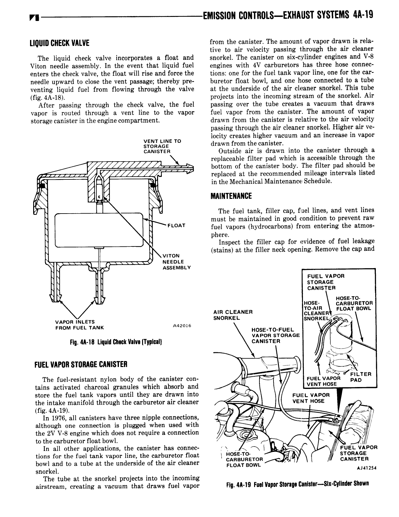
VI EMlSSl0Il C0llTll0LS EXHAllST SYSTEMS M IS LIQIIIII CIIEIIK VALVE from the canister The amount of vapor drawn i rela tive to air velocity passing through the air c eaner The liquid check valve incorporates a float and snorkel The canister on six cylinder engines and V 8 Viton needle assembly In the event that liquid fuel engines with 4V carburetors has three hose connec enters the check valve the float will rise and force the tions one for the fuel tank vapor line one for the car needle upward to close the vent passage thereby pre buretor float bowl and one hose connected to a tube venting liquid fuel from flowing through the valve at the underside of the air cleaner snorkel This tube fig 4A 18 projects into the incoming stream of the snorkel Air After passing through the check valve the fuel passing over the tube creates a vacuum that draws vapor is routed through a vent line to the vapor fuel vapor from the canister The amount of vapor storage canister in the engine compartment drawn from the canister is relative to the air velocity passing through the air cleaner snorkel Higher air ve locity creates higher vacuum and an increase in vapor E TO drawn from the canister CAMSTER Outside air is drawn into the canister through a replaceable filter pad which is accessible through the M bottom of the canister body The filter pad should be lv replaced at the recommended mileage intervals listed n a 1 ed I I N I I in the Mechanical Maintenance Sch u e uq I u y E MAINTENANCE g r V V I The fuel tank filler cap fuel lines and vent lines must be maintained in good condition to prevent raw E FL I iI e apors hydrocarbons from entering the atmos Inspect the filler cap for evidence of fuel leakage E I I www stains at the filler neck opening Remove the cap and uesnts N Y g Asssmstv I I I Fuel vapon I I I l sronacs I L I I camsren V I p H0SE ggggiigzron AIR ccemzn QEQISER L vnon mtars Mmm N RKEL N KE Faom sus unix H sE T FUEL Is upon sronacs Flg IA 16 Llquld Chuck llalv TyplcaI cmisren run vmn stance clmstrn g The fuel resistant nylon body of the canister con Fun VAPISIII ELIBYER tains activated charcoal granules which absorb and Q VE SE store the fuel tank vapors until they are drawn into uEI yAp0R the intake manifold through the carburetor air cleaner VENT HOSE og 4A 19 J g In 1976 all canisters have three nipple connections ij P i although one connection is plugged when used with lll the 2V V 8 engine which does not require a connection gi 4 f to the carburetor float bowl l J In all other applications the canister has connec yy H Fu5i vhvon tions for the fuel tank vapor line the carburetor float l H E mR l r GE bowl and to a tube at the underside of the air cleaner IE sgi BOWL r CA ISTER snorkel l2 The tube at the snorkel projects into the incoming airstream creating a vacuum that draws fuel vapor Fl Il 19 FMI VI rSl0I I I Clnitllr S X I y IId r87l Un