Ford Parts Wiki | GM Parts Wiki
Home | Search | Browse | Marketplace | Messages | FAQ | Guest
|
Technical Service Manual January 1975 |
|
Prev
 Next
Next
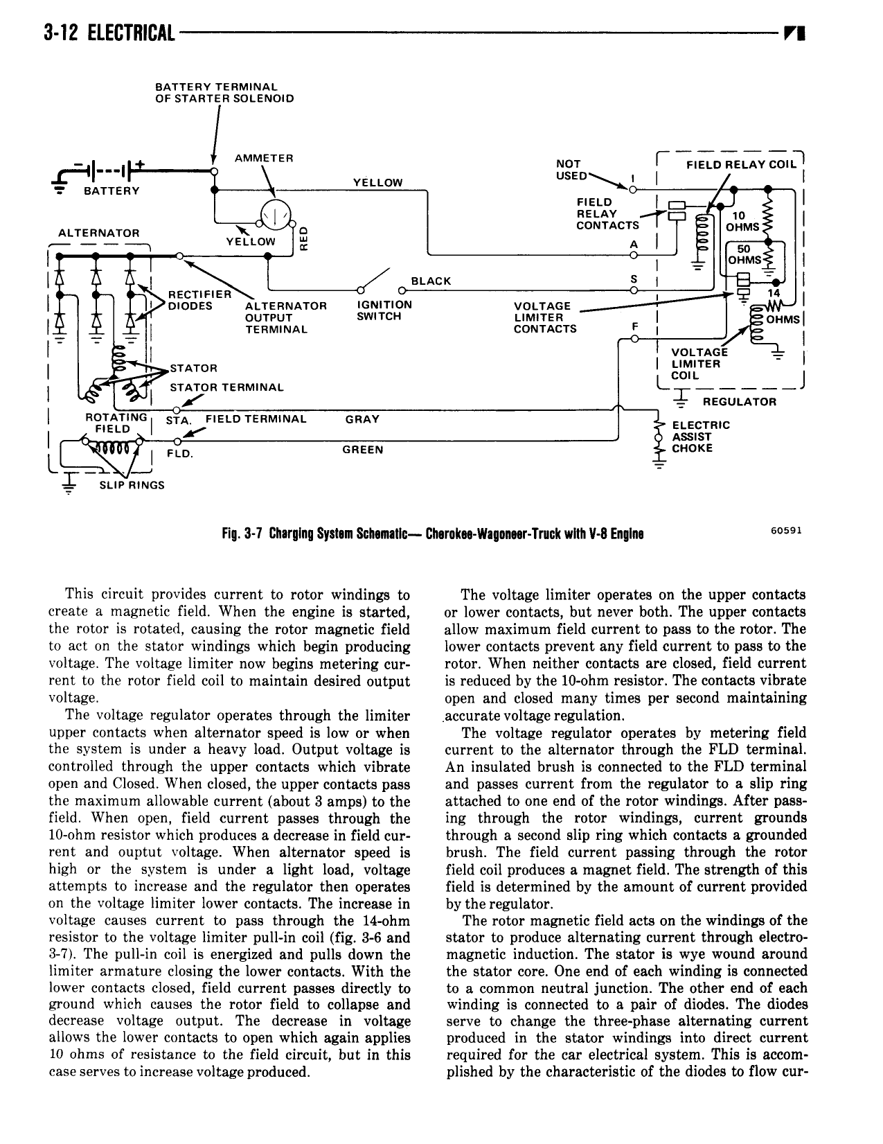
3 IZ ELECTRICAL VI sursav rsnmmai o sranrsn sotsnono II I AMMETER Ig I Finn Rztav coiq 7 EATTERV vEu 0w l l new I I A I 0 nzrav zr I Atrenuaron T Ts I j vzi Low g A I l T l I A A A I stacx S 1 I azcrmzn I Q 14 I I I monss Auanwrron ioumon vouacs A A A cutout SWITCH LIMITER I gHMs I I reammai comacrs I 3 I I was T I T V snrrcn rsnMmAi L L I I l I nscutaron nonmnc STA new rsnmowu cnav E E Imc I new A I L I FLD susan cracks sue amos H 3 7 l ru nu Syshm Sub mIln l2t mk vlaqan r Tnck wmi v 8 Englm 6 59 This circuit provides current to rotor windings to The voltage limiter operates on the upper contacts create a magnetic field When the engine is started or lower contacts but never both The upper contacts the rotor is rotated causing the rotor magnetic field allow maximum field current to pass to the rotor The to act on the stator windings which begin producing lower contacts prevent any field current to pass to the voltage The voltage limiter now begins metering cur rotor When neither contacts are closed field current rent to the rotor field coil to maintain desired output is reduced by the 10 ohm resistor The contacts vibrate voltage open and closed many times per second maintaining The voltage regulator operates through the limiter accurate voltage regulation upper contacts when alternator speed is low or when The voltage regulator operates by metering field the system is under a heavy load Output voltage is current to the alternator through the FLD terminal controlled through the upper contacts which vibrate An insulated brush is connected to the FLD terminal open and Closed When closed the upper contacts pass and passes current from the regulator to a slip ring the maximum allowable current about 3 amps to the attached to one end of the rotor windings After pass field When open field current passes through the ing through the rotor windings current grounds 10 ohm resistor which produces a decrease in field cur through a second slip ring which contacts a grounded rent and ouptut voltage When alternator speed is brush The field current passing through the rotor high or the system is under a light load voltage field coil produces a magnet field The strength of this attempts to increase and the regulator then operates field is determined by the amount of current provided on the voltage limiter lower contacts The increase in by the regulator voltage causes current to pass through the 14 ohm The rotor magnetic field acts on the windings of the resistor to the voltage limiter pull in coil fig 3 6 and stator to produce alternating current through electro 3 7 The pull in coil is energized and pulls down the magnetic induction The stator is wye wound around limiter arrnature closing the lower contacts With the the stator core One end of each winding is connected lower contacts closed field current passes directly to to a common neutral junction The other end of each ground which causes the rotor field to collapse and winding is connected to a pair of diodes The diodes decrease voltage output The decrease in voltage serve to change the three phase alternating current allows the lower contacts to open which again applies produced in the stator windings into direct current 10 ohms of resistance to the field circuit but in this required for the car electrical system This is accom case serves to increase voltage produced plished by the characteristic of the diodes to flow cur