Ford Parts Wiki | GM Parts Wiki
Home | Search | Browse | Marketplace | Messages | FAQ | Guest
|
Technical Service Manual January 1975 |
|
Prev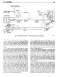
 Next
Next
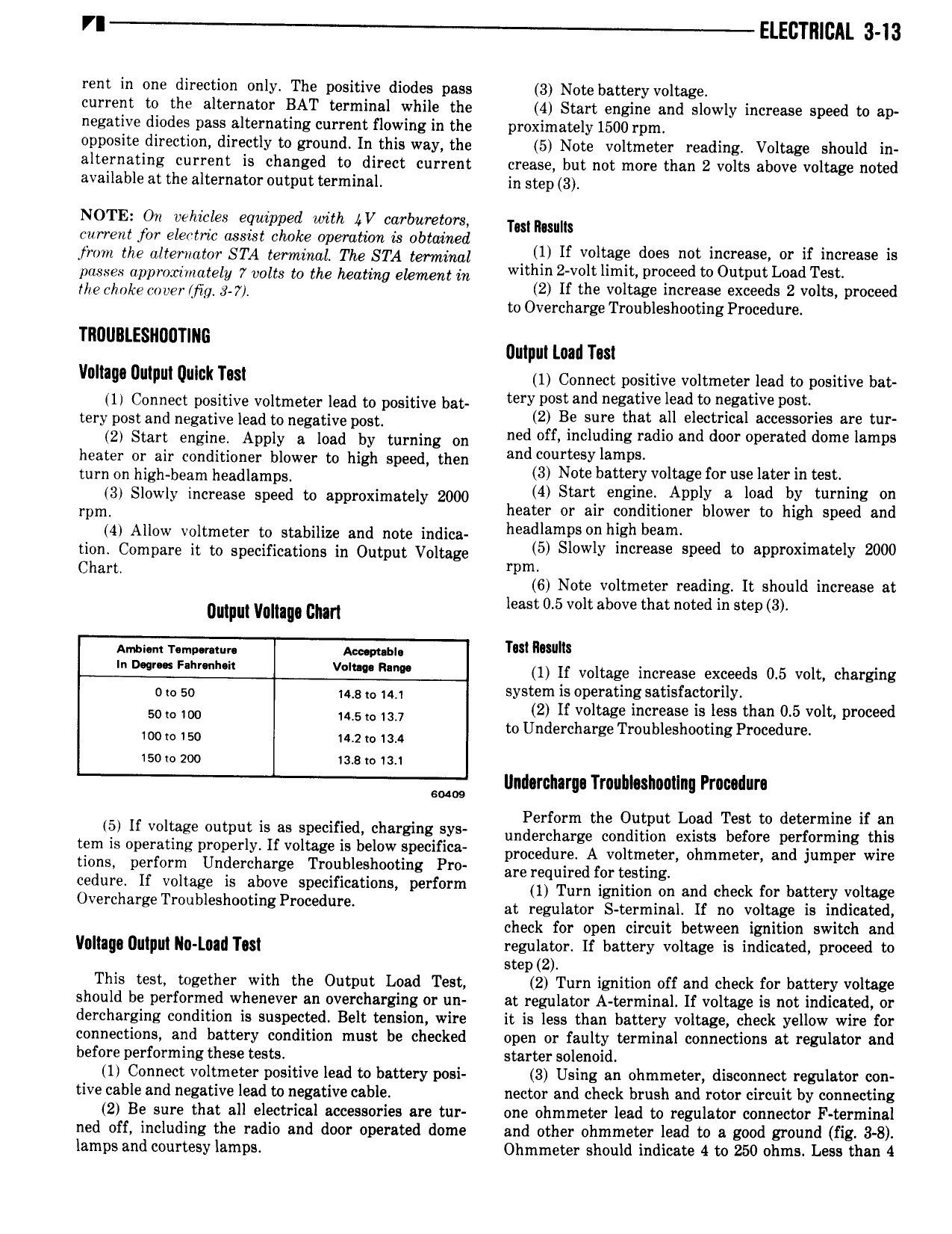
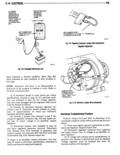
VI ELECTRICAL 3 13 rent in one direction only The positive diodes pass 3 Note battery voltage current to the alternator BAT terminal while the 4 Start engine and slowly increase speed to ap negative diodes pass alternating current flowing in the proximately 1500 rpm opposite direction directly to ground In this way the 5 Note voltmeter reading Voltage should in alternating current is changed to direct current crease but not more than 2 volts above voltage noted available at the alternator output terminal in step 3 NOTE On vehicles equipped with V carburetors Tulmsuln current for electric assist choke operation is obtained l v the alternator STA terminal To sm tmittl ll if mage dm mt e or m mo approximately 7 volts to to telling element it w 2 v l l 2 d 0 Led Tm theCh k t lc g 3 y 2 lf the voltage increase exceeds 2 volts proceed to Overcharge Troubleshooting Procedure TRUUBLESIIDUTING amp mad Tut Vlllilll UlIl I l ulllck TBI 1 Connect positive voltmeter lead to positive bat 1I Connect positive voltmeter lead to positive bat wry pim and negatlve lead nfig itlve lm tert post and negative lead tonegative post 2 Be sure that all elgcgrlca accessgrtiles arf tur 2 Start engine Apply a load by turning on ned off mcludlng radio an oor operate ome amps heater or air conditioner blower to high speed then and 5yi a lpS I f 1 t te t turn on high beam headlamps 4 S3 a Elly v agi Or usf zelilln ts 3 Slowly increase speed to approximately 2000 l rl engl ppy 8 03 y ummg on rpm heater or alr conditioner blower to high speed and 4 Allow voltmeter to stabilize and note indica headlsmvs n hlgh beam I 00 tion Compare it to specifications in Output Voltage 5 Sl Wly n r S spwd t appmxlmatey 20 Ch t rpm ar 6 Note voltmeter reading It should increase at amp vom chan least 0 5 volt above that noted in step 3 Amston r mp m Ao p l Tm llwlm F V 1 If voltage increase exceeds 0 5 volt charging O 0 50 48 0 lm system is operating satisfactorily ml 2 If voltage increase is less than 0 5 volt proceed o too 14 slo1s v to Undercharge Troubleshooting Procedure 100to150 14 2 o1 4 15Dw200 ia sl 1 1 sms llmlarcllarga Trnullloshnctlnq Pracadura Perform the Output Load Test to determine if an l l lf mliage mltput ls as p l d hm gm ys undercharge condition exists before performing this tem ls operating properly If voltage ls below speciflca procedum A voltmeter Olimmetert and jumper wire tions perform Undercharge Troubleshooting Pro are required t m t Sting i cedure If voltage is allove specifications perform ll Tum ignition on and chggk Ol battery voltage OvmhergeT bl h P ed at regulator solmlnll If no voltage is lndltmd check for open circuit between ignition switch and Voltuuu Uuluut Nu g 1 ugi regulator If battery voltage is indicated proceed to step 2 This test together with the Output Load Test 2 Turn ignition off and check for battery voltage should be performed whenever an overcharging or un at regulator A terminal lf voltage is not indicated or dercharging condition is suspected Belt tension wire it is less than battery voltage check yellow wire for connections and battery condition must be checked open or faulty terminal connections at regulator and before performing these tests starter solenoid I 1 Connect voltmeter positive lead to battery posi 3 Using an ohmmeter disconnect regulator con tive cable and negative lead to negative cable nector and check brush and rotor circuit by connecting 2 Be sure that all electrical accessories are tur one ohmmeter lead to regulator connector F terminal ned off including the radio and door operated dome and other ohmmeter lead to a good ground fig 3 8 lamps and courtesy lamps Ohmmeter should indicate 4 to 250 ohms Less than 4