Ford Parts Wiki | GM Parts Wiki
Home | Search | Browse | Marketplace | Messages | FAQ | Guest
|
Technical Service Manual January 1975 |
|
Prev
 Next
Next
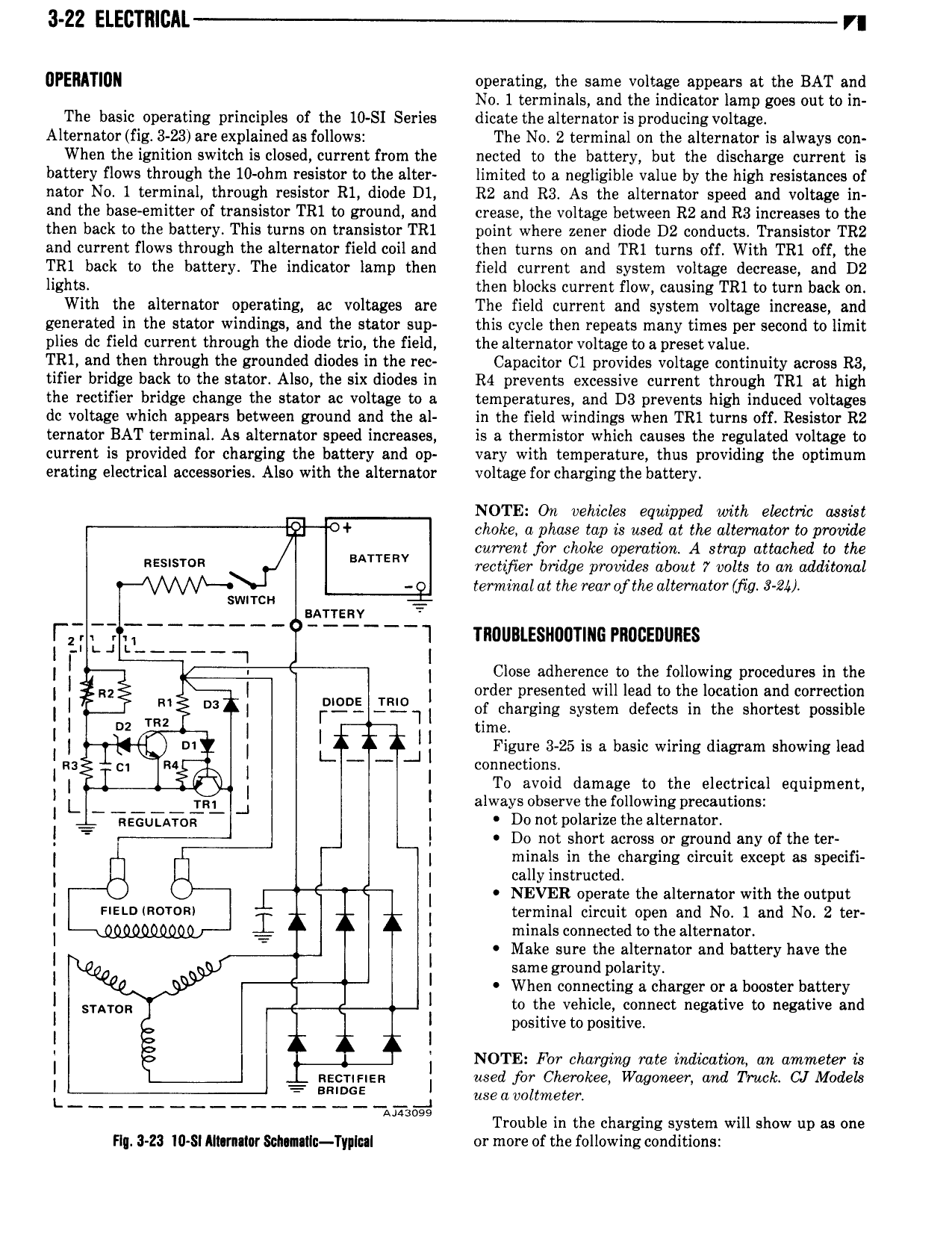
3 22 ELECTIllCAL VI UPEMTIUN operating the same voltage appears at the BAT and No 1 terminals and the indicator lamp goes out to in The basic operating principles of the 10 SI Series dicate the alternator is producingvoltage Alternator fig 3 23 are explained as follows The No 2 terminal on the alternator is always con When the ignition switch is closed current from the nected to the battery but the discharge current is battery flows through the 10 ohm resistor to the alter limited to a negligible value by the high resistances of nator No 1 terminal through resistor R1 diode D1 R2 and R3 As the alternator speed and voltage in and the base emitter of transistor TR1 to ground and crease the voltage between R2 and R3 increases to the then back to the battery This turns on transistor TR1 point where zener diode D2 conducts Transistor TR2 and current flows through the alternator field coil and then turns on and TR1 turns off With TR1 off the TR1 back to the battery The indicator lamp then field current and system voltage decrease and D2 lights then blocks current flow causing TR1 to turn back on With the alternator operating ac voltages are The field current and system voltage increase and generated in the stator windings and the stator sup this cycle then repeats many times per second to limit plies dc field current through the diode trio the field the alternator voltage to a preset value TR1 and then through the grounded diodes in the rec Capacitor C1 provides voltage continuity across R3 tifier bridge back to the stator Also the six diodes in R4 prevents excessive current through TR1 at high the rectifier bridge change the stator ac voltage to a temperatures and D3 prevents high induced voltages dc voltage which appears between ground and the al in the field windings when TR1 turns off Resistor R2 ternator BAT terminal As alternator speed increases is a thermistor which causes the regulated voltage to current is provided for charging the battery and op vary with temperature thus providing the optimum erating electrical accessories Also with the alternator voltage for charging the battery NOTE On vehicles equipped with electric asskt 51 choke a phase tap is used at the alternator to provide current for choke operation A strap attached to the RE I I I BATTERV rectifier bridge provides about 7 volts to on additonol terminal at the rear ofthe alternator Mig 8 2 swrrcn sarrenv l I 1 I l TROUBLESHUUTIIIG PROCEDURES I I vi I Close adherence to the following procedures in the I I I I order presented will lead to the location and correction I I 1 I IFXELII of charging system defects in the shortest possible D2 time I I I J I Figure 3 25 is a basic wiring diagram showing lead as connections I I ga I I To avoid damage to the electrical equipment I I I RI J I always observe the following precautions I QQUTAEQ I Do not polarize the alternator I I Do not short across or ground any of the ter I I minals in the charging circuit except as specifi I I cally instructed I I NEVER operate the alternator with the output I snnnmorom I I terminal circuit open and No 1 and No 2 ter I I minals connected to the alternator Make sure the alternator and battery have the I r I I I I r I same ground polarity I I When connecting a charger or a booster battery I SIATOR I to the vehicle connect negative to negative and positive to positive I I I NOTE For charging rate indication an dmrrieter is I Rsorinsn I used for Cherokee Wdgoneer and Truck CJ Models I 2 f I useavoltmeter Manga Trouble in the charging system will show up as one Flu 3 Z3 I0 Sl Almntlor Sonnllo Typical or more of the following conditions