Ford Parts Wiki | GM Parts Wiki
Home | Search | Browse | Marketplace | Messages | FAQ | Guest
|
Technical Service Manual January 1975 |
|
Prev
 Next
Next
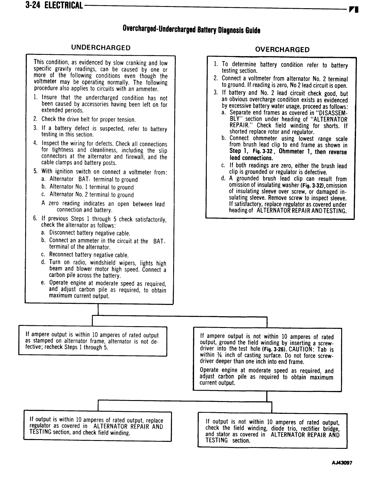
3 Z4 ELEGTIIIOAL r flvernharged Undercharged Battery Diagnosis GuIrl UNDERCHARGED OVERCHARGED This condition as evidenced by slow cranking and low I To determine battery condition refer to battery specific gravity readings can be caused by one or testing section more of the feh w ne Q d t 0 even though the 2 comreet a vortmeter from alternator no ztemrrrrar vurmeter may be ooeratmc normally The felhwunz to gmu u rrreaarng as zero uozreau more is open procedure also applies to circuits with an ammeter 3 H bmw and NQ 2 md idmm check gum but 1 Insure that the underrchargedcondition has not an obvious overcharge condition exists as evidenced been caused by accessories having been Ielt on for by excessive battery water usage proceed as follows extended periods a Separate end frames gs covered BLY section under eading o Z d b l t rtmrnxr check nero winding mr sirens rr 3 If a battery defect rs suspected refer to battery shaded repme mm and yegumor l l b Connect ohmmeter using lowest range scale 4 Inspect the wiring for defects Check all connections from bf l lead CND to Bhd lT ITI BS shown In for tightness and cleanliness including the slip Step I Fig 3 32 Uhmmeter I then reverse connectors at the alternator and firewall and the lead connections l7 9 CIBIITPS and b ll IY I 0 l c ll both readings are zero either the brush lead 5 With ignition switch on connect a voltmeter from d glPg l I gdi7drL h gt i dg t m from E m 1 NBA term m gmund omissionof insulating washer Fr 3 3 J omission tematm mmlna gmund of insulating sleeve over screw or damaged in c Alternator No 2 terminal to ground sulating sleeve Remove screw to inspectdsleege A d n t D t d Ifsatis actory repace regu ator as covere un er Z 0 Ci n w ea nearirrrger Arrenuaron neexrnnuorzstruo 6 lf previous Steps I through 5 check satisfactorily check the alternator as follows a Disconnect battery negative cable b Connect an ammeler in the circuit at the BAT terminal of the alternator c Reconnect battery negative cable d Turn on radio windshield wipers lights high beam and blower motor high speed Connect a carbon pile across the battery e Operate engine at moderate speed as required and4adiust carbon pile as required to obtain maximum current output lf ampere output is within IU amperes of rated output lf ampere output is not within 10 amperes of rated as stamped on alternator frame alternator is not de output ground the field winding by inserting a screw fective recheck Steps I through 5 driver into the test hole FIq 3 Z6 CAUTION Tab is within inch of casting surface Do not force screw driver deeper than one inch into end frame Operate engine at moderate speed as required and adjust carbon pile as required to obtain maximum current output If output is within I0 amperes of rated output replace lf output is not within I0 amperes of rated output regulator as covered in ALTERNATOR REPAIR AND check the field winding diode trio rectifier bridge TESTING section and check field winding and stator as covered in ALTERNATOR REPAIR AND TESTING section Auaow