Ford Parts Wiki | GM Parts Wiki
Home | Search | Browse | Marketplace | Messages | FAQ | Guest
|
Technical Service Manual January 1975 |
|
Prev
 Next
Next
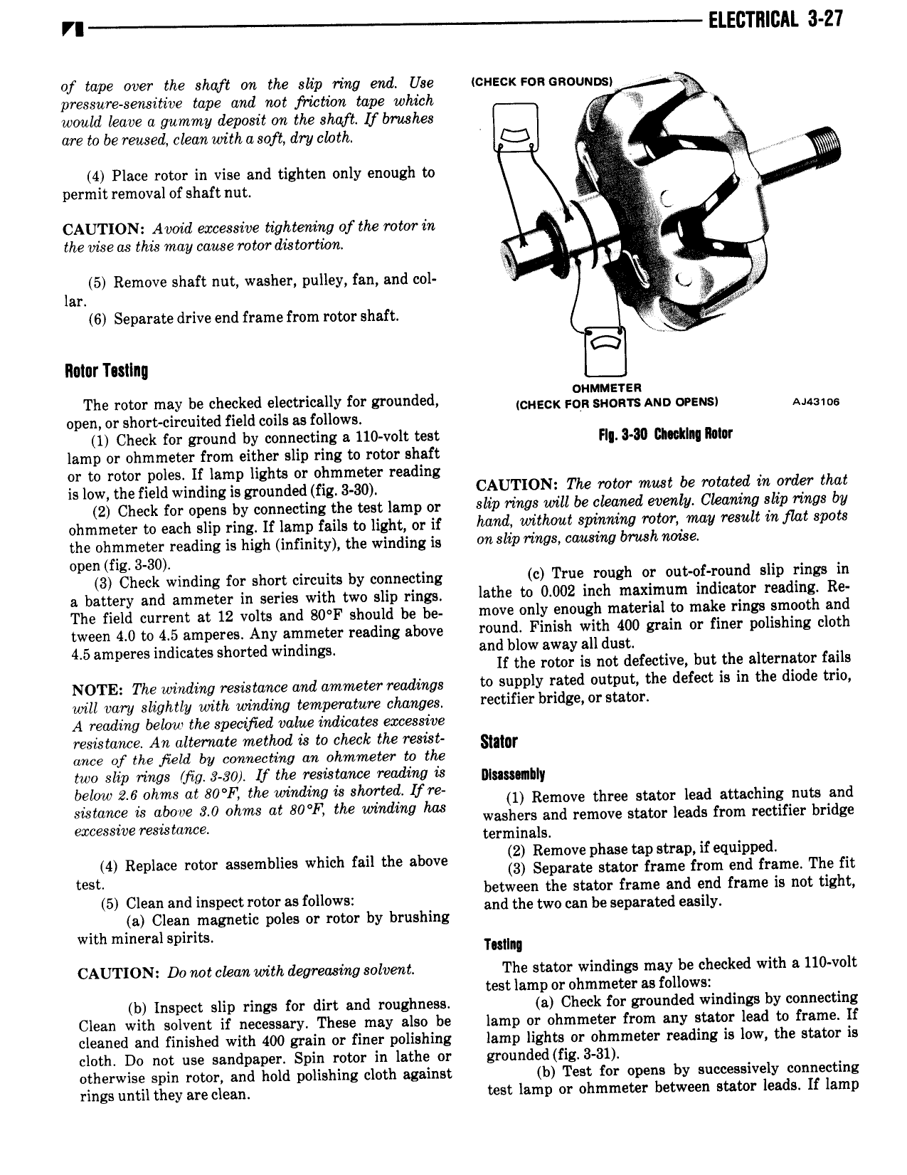
VI ELECTRICAL 3 27 of tape over the shaft on the slip ring end Use icuscx son csounosi pressure sensitive tape and not frwtion tape which would leave a gummy deposit on the shaft lf brushes are to be reused clean with a soft dry chath s W V u min 4 Place rotor in vise and tighten only enough to V permit removal of shaft nut E l ve C CAUTION Avoid excessive tightening ofthe rotor in the vise as this may cause rotor distortibn 4 5 Remove shaft nut washer pulley fan and col l gx lar 6 Separate drive end frame from rotor shaft llolur T sllng E The rotor may be checked electrically for grounded NECK 5 AND WENSI Mums open or short circuited field coils as follows 1 Check for ground by connecting a 110 volt test F 3 99 mmm my lamp or ohmmeter from either slip ring to rotor shaft or to rotor poles lf lamp lights or ohmmeter reading is low the field winding is grounded fig 3 80 CAUTl0N The TON mils be 0l l l lll l lllal 2 Check for opens by connecting the test lamp or 8llP l l VlU8 will be l Wl il WVllil Cleivlltlll Sllll l l9 bl ohmmeter to each slip ring If lamp fails to light or if Mild wlllwul Sltlmlltlil WWE tml fewll l7l flat 8P0l l the ohmmeter reading is high infinity the winding is Wl llP rims W 8l7ll7 lmulll Wl8 open fig 3 30 3 Check winding for short circuits by connecting ic True mlllll 0 0lli 0f l d 5llP l ll lB lll a battery and ammeter in series with two slip rings lathe to 0002 inch Xl l m l dl i l 0l l 9 dl E R The field current at 12 volts and 80 F should be be lll0V only 1Ell m 1 l l l l l l 8 Smwlh and tween 4 0 to 4 5 glmpgrgg Any nmmegey reading above round Finish with 400 grain or finer polishing cloth 4 5 nmperes indicates shorted windings and blow away all dust If the rotor is not defective but the alternator fails NQTE The winding nesmeme me ammem readings to supply rated output the defect is in the diode trio waz tan slightly with winding temperature changes rectifier bridge r a r A reading below the specified value indicates excessive resistance An alternate method is to check the resist sm ance of the field by connecting an ohmmeter to the two slip rings Mg 3 30 If the resistance reading is muammy below 2 6 ohms at 80 F the wimiing is shorted fre 0 1 Remove three stator lead attaching nuts and wwwa is almve 3 0 Ohms at 80 E the wmdmg has washers and remove stator leads from rectifier bridge excessive resistance terminals 2 Remove phase tap strap if equipped t st 4 Replace rotor assemblies which fail the above 3 Separate Mawr frame from end frame The fit between the stator frame and end frame is not tight 5 Clean and inspect rotor as follows and the two can be Separated easily a Clean magnetic poles or rotor by brushing with mineral spirits Tuilng CAUTION Do not clean with degreasing solvent The stator windings may be checked with a 110 volt test lamp or ohmmeter as follows b Inspect slip rings for dirt and roughness a Check for grounded windings by connecting Clean with solvent if necessary These may also be lamp or ohmmeter from any stator lead to frame lf cleaned and finished with 400 grain or finer polishing lamp lights or ohmmeter reading is low the stator is cloth Do not use sandpaper Spin rotor in lathe or grounded fig 3 31 otherwise spin rotor and hold polishing cloth against b Test for opens by successively connecting rings until they are clean test lamp or ohmmeter between stator leads If lamp