Ford Parts Wiki | GM Parts Wiki
Home | Search | Browse | Marketplace | Messages | FAQ | Guest
|
Technical Service Manual January 1975 |
|
Prev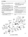
 Next
Next
142465
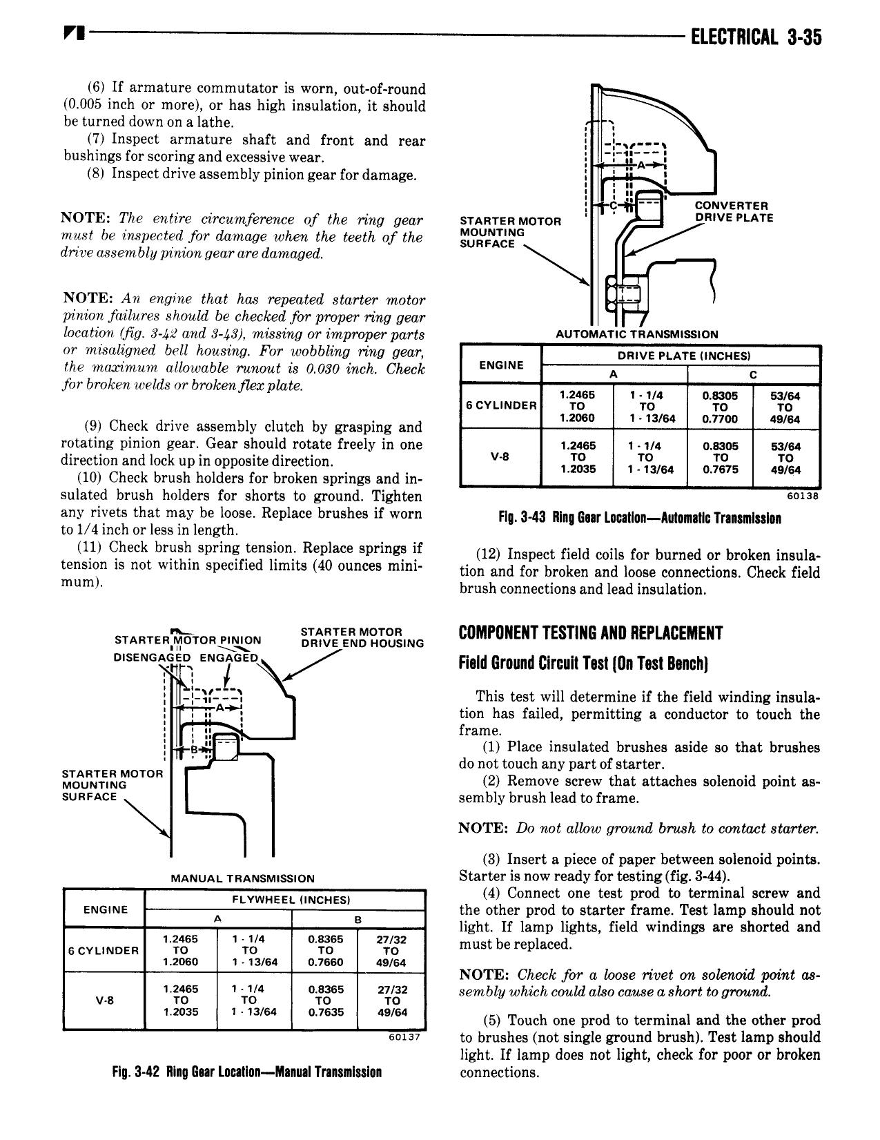
VI ELECTRICAL 3 35 6 If armature commutator is worn out of round 0 005 inch or more or has high insulation it should be turned down on a lathe 7 Inspect armature shaft and front and rear bushings for scoring and excessive wear Q 8 Inspect drive assembly pinion gear for damage 5 Il I l H couvenrsn NOTE The entire circumference of the mng gear srmrzn Moron VE PLATE mast be inspected for damage when the teeth of the gggg gc drive assembly pinion gear are damaged NOTE An engine that has repeated starter motor pinion failures should be checked for proper ring gear location fig 3 42 and 8 43 missing orr improper paris AUTOMATIC rnmsuussiou or misaligned bell housing For wobbling ring gear nmvs narsuncnssy the inaximuin allowable runout is 0 030 inch Check jbr broken welds or broken flea plate 142465 U4 D sms wu s cvunnsn ro 1 Tau 1 0 TF 1 20so 1 so 7700 as sa 9 Check drive assembly clutch by grasping and 0 rotating pinion gear Gear should rotate freely in one 1 24ss 1 1 4 amos sa 64 direction and lock up in opposite direction v Lggw 1 7 64 Jigs gg 10 Check brush holders for broken springs and in sulated brush holders for shorts to ground Tighten any rivets that may be loose Replace brushes if worn f 3 43 qu qn Au gm y n m to I 4 inch or less in length 11 Check brush Sims i Revlm v i if 12 xmpen new mus for burned or broken amia t Si is mt within Specified limits 40 mlnl tion and for broken and loose connections Check field m ml brush connections and lead insulation STARTERWTD m5 wgB ING IDMPIJNENT TESTING ANI1 REPLACEMENT s Flald Ground Glrcull Test Un Tm Bunch l l I E lZ IZ L This test will determine if the field winding insula A tion has failed permitting a conductor to touch the 5 H frame l Q 1 Place insulated brushes aside so that brushes do not touch any part of starter STARTER M T R 2 Remove screw that attaches solenoid point as Moummc surance sembly brush lead to frame NOTE Do not allow ground brush to contact starter 3 Insert s piece of paper between solenoid points MANUAL Tnausmnssmu Sfaifgfg 0W ready TF testing 8 3 44 I d onnect one es pro rmma screw an FWWHEEL INCHES the other prod to starter frame Test lamp should not n light If lamp lights field windings are shorted and 1 1 4 mass 27 32 s cvuuosn 1 ig 1 0 xw gf must be replaced mos 1 i on 4 so NOTE Cheek for a bose rivet on soknoid pcnnt oa I 2 65 1 1 4 0 8365 27 12 sembly which could also cause a short to gmumi v s ro TO T0 TO mms 1 13 64 7635 49 64 5 Touch one prod to terminal and the other prod wv to brushes not single ground brush Test lamp should light If lamp does not light check for poor or broken Flu 342 Rlnq Gar ln lIan IIanu I Trmnlsslun connections