Ford Parts Wiki | GM Parts Wiki
Home | Search | Browse | Marketplace | Messages | FAQ | Guest
|
Technical Service Manual January 1975 |
|
Prev
 Next
Next
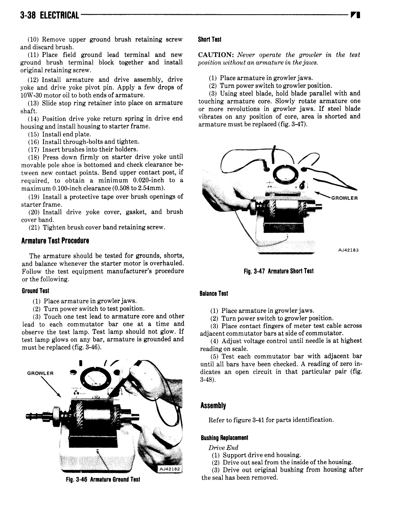
3 38 ELEcTmcAL n 10 Remove upper ground brush retaining screw Shnrl Ital and discard brush ll Place field ground lead terminal and new CAUTION Never operate the growler in the test ground brush terminal block together and install position withoutcm armature in thejuws original retaining screw 12 Install armature and drive assembly drive U Place 3 m3t 1Y in srowleriaws yoke and drive yoke pivot pin Apply a few drops of 2 Turniwwerswitcht er0w1erp si i0n i W 3g rndmr dii to both ends of ai mature 3 Using steel blade hold blade parallel with and 13 Slide stop ring retainer into place on armature i0 l l E aFm8 9 01 Slowly 1 0 f 1 m l1 1 0 shaft or more revolutions in growler jaws If steel blade M position drive yoke return Spring in drive end vibrates on any position of lcore area is shorted and housing and install housing to starter name armawre must he renlmd f z 3 47 15 Install end plate I6 Install through bolts and tighten 17 Insert brushes into their holders 18 Press down firmly on starter drive yoke until 0 movable pole shoe is bottomed and check clearance be fl tween new contact points Bend upper contact post if required to obtain a minimum 0 020 inch to a maximum 0 100 inch clearance 0 508 to 2 54mm E if l 19 Install a protective tape over brush openings of XGROWLER starter frame V QU ug if 20 Install drive yoke cover gasket and brush C cover band V Y 21 Tighten brush cover band retaining screw i Armalura Tas Prnculura Eno The armature should be tested for grounds shorts 2183 and balance whenever the starter motor is overhauled Follow the test equipment manufacturers procedure Flu 3 I7 Annalurl Shari Tusl or the following 6 ll ml Balamsn Tm 1 Place armature in growler jaws 2 Turn power switch to test position 1 Place armarure in growior jawo 3 Touch one test lead to armature core and other 2 Tum power Switch to gmwior position lead t each mmutat r bar at A time and 3 Place contact fingers of meter test cable across Observe the teal lamp Test lamp alwllld llpt gl w lf adjacent commutator bars at side of commutator teal lamp glows ll any pal armamre la gmunded and 4 Adjust voltage control until needle is at highest must be replaced fig 3 46 reading on Sonia 5 Test each commutator bar with adjacent bar I until all bars have been checked A reading of zero in n0w n 9 Q W dicates an open circuit in that particular pair fig 3 48 g Assembly I xw Refer to figure 3 41 for parts identification 5 Bushlnq Ihplaumam l i 5 omg End ar 1 Support drive end housing n 2 Drive out seal from the inside ofthe housing A 2l 2 3 Drive out original bushing from housing after rid 3 45 hmm gmimi noi the seal has been removed