Ford Parts Wiki | GM Parts Wiki
Home | Search | Browse | Marketplace | Messages | FAQ | Guest
|
Technical Service Manual January 1975 |
|
Prev
 Next
Next
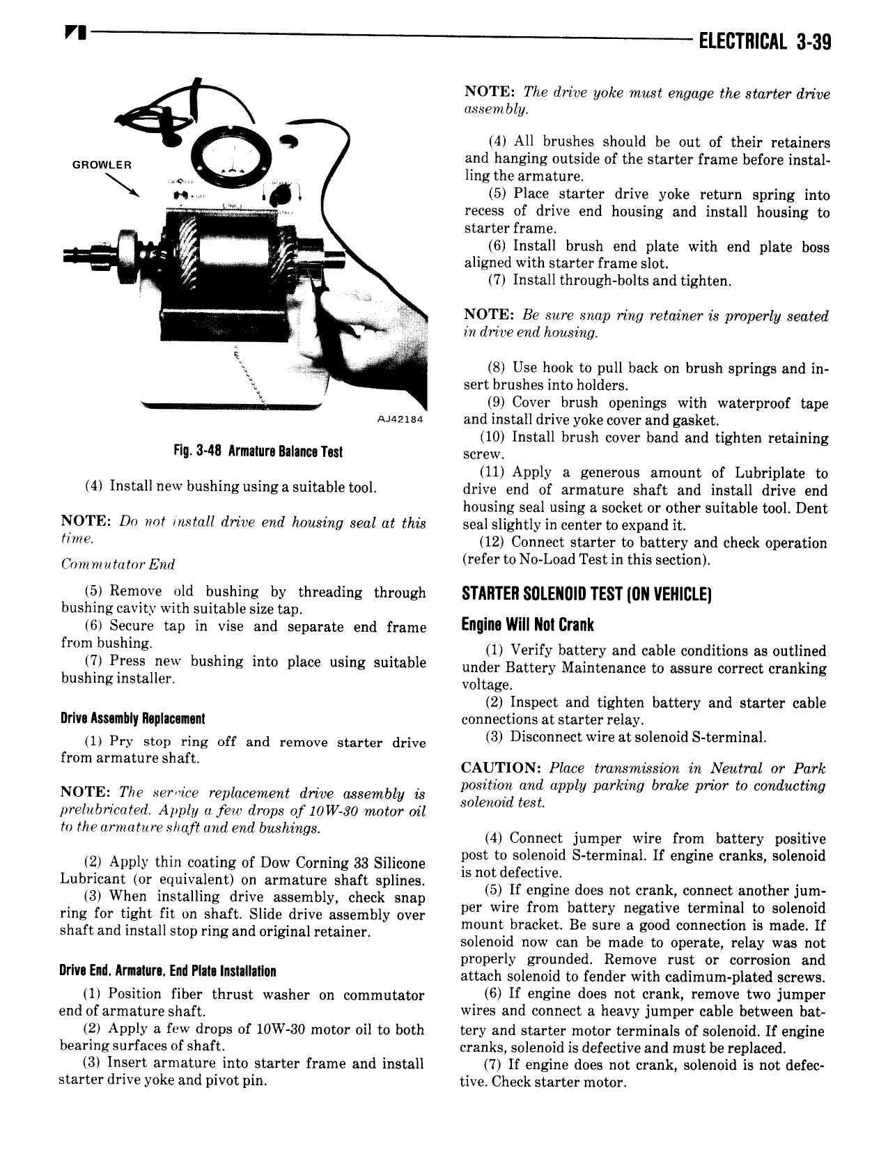
Eircrmcni 3 as NOTE The drive yoke mast engage the starter drive assembly i Q 4 All brushes should be out of their retainers GROWLER Q and hlanging outside of the starter frame before instal H W ingt earmature A A V 5 Place starter drive yoke return spring mto N l 1 recess of drive end housing and install housing to starter frame 6 nstall brush end plate with end plate boss s r I 7 7 aligned with starter frame slot A 7 Install through bolts and tighten t hi NOTE Be sure snap ring retainer is properly seated U V in drive end housing s ii Q 8 Use hook to pull back on brush springs and in 2 sert brushes into holders 9 Cover brush openings with waterproof tape Ahszisa and install drive yoke cover and gasket 10 Install brush cover band and tighten retaining Flg 348 Armnura Balancs Tas screw 11 Apply a generous amount of Lubriplate to 4 Install new bushingusingasuitable tool drive end of armature shaft and install drive end housing seal using a socket or other suitable tool Dent NOTE Do not install drive end housing seal at this seal slightly in center to expand it time 12 Connect starter to battery and check operation com mu mmf End refer to No Load Test in this section 5 Remove old bushing by threading through STMITEII SOLENOID TEST UN VEHICLE bushing cavity with suitable size tap 6 Secure tap in vise and separate end frame EMI wm NUI crank mm bunnns 1 Verify battery and cable conditions as outlined 7 regs new bushmg lm place usmg Smteble under Battery Maintenance to assure correct cranking bushing installer Vonage 2 Inspect and tighten battery and starter cable Drlvu kssumbly llaplanamuni connections at starter relay V 1 Pry stop ring off and remove starter drive 3 Disconnect wire atsolenoid S term1naI h morrow Place tmhsnitmn in Neutral or Park NOTE The service replacement drive assembly is SSZQZZ jig apply pwkmg brake prim um uc ng prelubricoted Apply u few drops 0f10W 80 motor oil to the ormatnre s rajtmzd end bushings 4 Connect jumper Wim from battery positive 2 Apply thin coating of Dow Corning 33 Silicone lgoflgfgeilgglx d S m mmal If engine cmnkl solenoid Lubricant Or Fqmvalgnt ln immature shaft splines 5 If engine does not crank connect another jum 3r When installing drive assembly check snap per wire from battery negative terminal to solenoid ring for tight fit on shaft Slide drive assembly over mount bracket Be sure a good connection is made If shaft and install stop ring and original retainer solenoid now can be made to operate relay was not properly grounded Remove rust or corrosion and r v Ent Arnnvrr ni P lnsnlnllvn attach stiehhiri to render with ttdimiim plated screws il Position fiber thrust washer ch commutattr 6 if engine does not crank remove two Jumper and of armatum Shar wires and connect a heavy Jumper cable between bat 2 Apply a few drops of 10W 30 motor oil to both tery and starter motor terminals of solenoid If engine bearing surfaces of shaft cranks solenoid is defective and must be replaced 3 Insert armature into starter frame and install 7 If engine does not crank solenoid is not defec starter drive yoke and pivot pin tive Check starter motor