Ford Parts Wiki | GM Parts Wiki
Home | Search | Browse
|
Technical Service Manual January 1975 |
|
Prev

 Next
Next
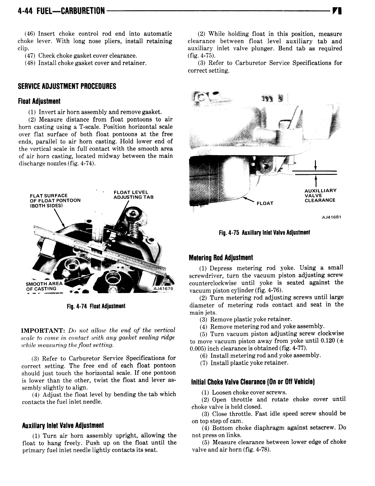
4 44 FUEL CAllBllllETl0ll Y 46 Insert choke control rod end into automatic 2 While holding float in this position measure choke lever With long nose pliers install retaining clearance between float level auxiliary tab and Nil auxiliary inlet valve plunger Bend tab as required 47 Check choke gasket cover clearance fig 4 75 48 Install choke gasket cover and retainer 3 Refer to Carburetor Service Specifications for correct setting SERVICE ADJUSTMENT PROCEDURES Q nm Anpimmm M 5 1 Invert air horn assembly and remove gasket i 2 Measure distance from float pontoons to air horn casting using a T scale Position horizontal scale 3 7 t i l over flat surface of both float pontoons at the free A ends parallel to air horn casting Hold lower end of M the vertical scale in full contact with the smooth area Wm W of air horn casting located midway between the main discharge nozzles fig 4 74 4 1 g iy s A i tf AUXILLIARV scar surmxcs F AT LEVEL or i oAr eomoou A S Us fi QQXEANCE BOTH sioes 0 Fl A Aiuesi e lg Fly 4 15 Auxlllary ln c1lIa v0Mlus1mlnl rg w Q i T lge if r fg V r Q Motoring llml llrlluslmanl r Aly y 1 Depress metering rod yoke Using a small J screwdriver turn the vacuum piston adjusting screw smoom AREA l counterclockwise until yoke is seated against the Ff sI N g V A 67 vacuum piston cylinder fig 4 76 2 Turn metering rod adjusting screws until large Fl 4 74 Fl0 lAllluslm nl diameter of metering rods contact and seat in the main jets 3 Remove plastic yoke retainer IMPORTANT Do not allow the end of the vertical gl em vB metemigfod ag ygke assembbf kwis mo fn come in contact with any gasket sealing ridge l l ms 3 S mg while mermwmg the Oat Setting to move vacuum piston away from yoke until 0 120 1 V V 0 005 inch clearance is obtained fig 4 77 3 Refer to Carburetor Service Specifications for 6 Installmemllng md and Y k emblY correct setting The free end of each float pontoon 7 I S aUpl tl y k retalnen should just touch the horizontal scale If one pontoon S eve em the e me me flee Md me as umm convent Clearance nn nr un von sembly slightly to align 4 Adjust the float level by bending the tab which U l 00Ben h k JOVEY sc contacts the Helmet needle 2 Open throttle and rotate choke cover until choke valve is held closed 3 Close throttle Fast idle speed screw should be f Mmm mm ww Mlummm on T5 Slgeolisoniaglioke diaphragm against setscrew Do 1 Turn air horn assembly upright allowing the not press on links float to hang freely Push up on the float until the 5 Measure clearance between lower edge of choke primary fuel inlet needle lightly contacts its seat valve and air horn fig 4 78

 Next
Next