Ford Parts Wiki | GM Parts Wiki
Home | Search | Browse
|
Technical Service Manual January 1975 |
|
Prev

 Next
Next
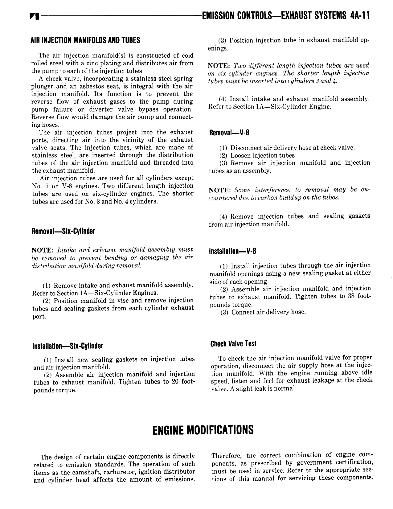
VI EN SS 0N CONTlIULS EXHAUST SYSTEMS Ml 11 MII INJECTIUN MINIFDLIJS MID TUBES 3 Position injection tube in exhaust manifold op enings The air injection manifold s is constructed of cold rolled steel with a zinc plating and distributes air from NOTE Tw dvferem length injection tubes we Med the pump to each of the injection tubes A check valve incorporating a stainless steel spring Onbxwcylmjgler mgmesi The Shorter mgm Uecmm tr 2 C plunger and an asbestos seat is integral with the air M 8 mmf emsened mm cylmderggandf injection manifold Its function is to prevent the reverse jew Of exhaust gases to the pump during 4 Install intake and exhaust manifold assembly pump failure or diverter valve bypass operation Reiettusmon1A y1 d rE z Reverse flow would damage the air pump and connect ing hoses The air injection tubes project into the exhaust g gyg ports directing air into the vicinity of the exhaust Val S98 S The i j tl0 tubes which M9 m d uf 1 Disconnectair delivery hose at check valve stainless steel are inserted through the distribution 2 Lggggnjnjgctjgn tubeo tubes of the air injection manifold and threaded into 3 Remove on injection manifold and injection the exhaust manifold tubes as an assembly Air injection tubes are used for all cylinders except No 7 on V 8 engines Two different length injection tubes are used on six cylinder enginest The Shorter N0TE Some Mterferencedtv renzovolbntay be en mbes are used fm N0 3 and N0 4 Cylinders countered due to carbon buil up ont e tu cs 4 Remove injection tubes and sealing gaskets from air injection manifold Ilnmaval Slx Cyllndor NOTE Intake and exhaust manifold assembly must n ja a n v 8 be removed to prevent bending or damaging the air dtstnbtttivn nwmfvld during removal ti Install injection tubes through the an injection manifold openings using a new sealing gasket at either 1 Remove intake and exhaust manifold assembly sldedeach epgilme ld d t Refert0Section1A Six CylinderEngin g ht ASST arr lujelijiicjjl njjam 0 b anwiggeg wet 2 Position manifold in vise and remove injection tu as to ex aus mam dg ten tu es tubes and sealing gaskets from each cylinder exhaust peunds rq e pom 3 Connect air delivery hose 1nuanaiaun six cyuinutr Gluck Valvv Tw 1 Install new sealing gaskets on injection tubes To check the air injection manifold valve for proper and air injection manifold operation disconnect the air supply hose at the injec 2 Assemble air injection manifold and injection tion manifold With the engine running above idle tubes to exhaust manifold Tighten tubes to 20 foot speed listen and feel for exhaust leakage at the check pounds torque valve A slight leak is normal The design of certain engine components is directly Therefore the correct combination of engine com related to emission standards The operation of such ponents as prescribed by government certification items as the camshaft carburetor ignition distributor must be used in service Refer to the appropriate sec and cylinder head affects the amount of emissions tions of this manual for servicing these components

 Next
Next