Ford Parts Wiki | GM Parts Wiki
Home | Search | Browse
|
Technical Service Manual January 1975 |
|
Prev
 Next
Next
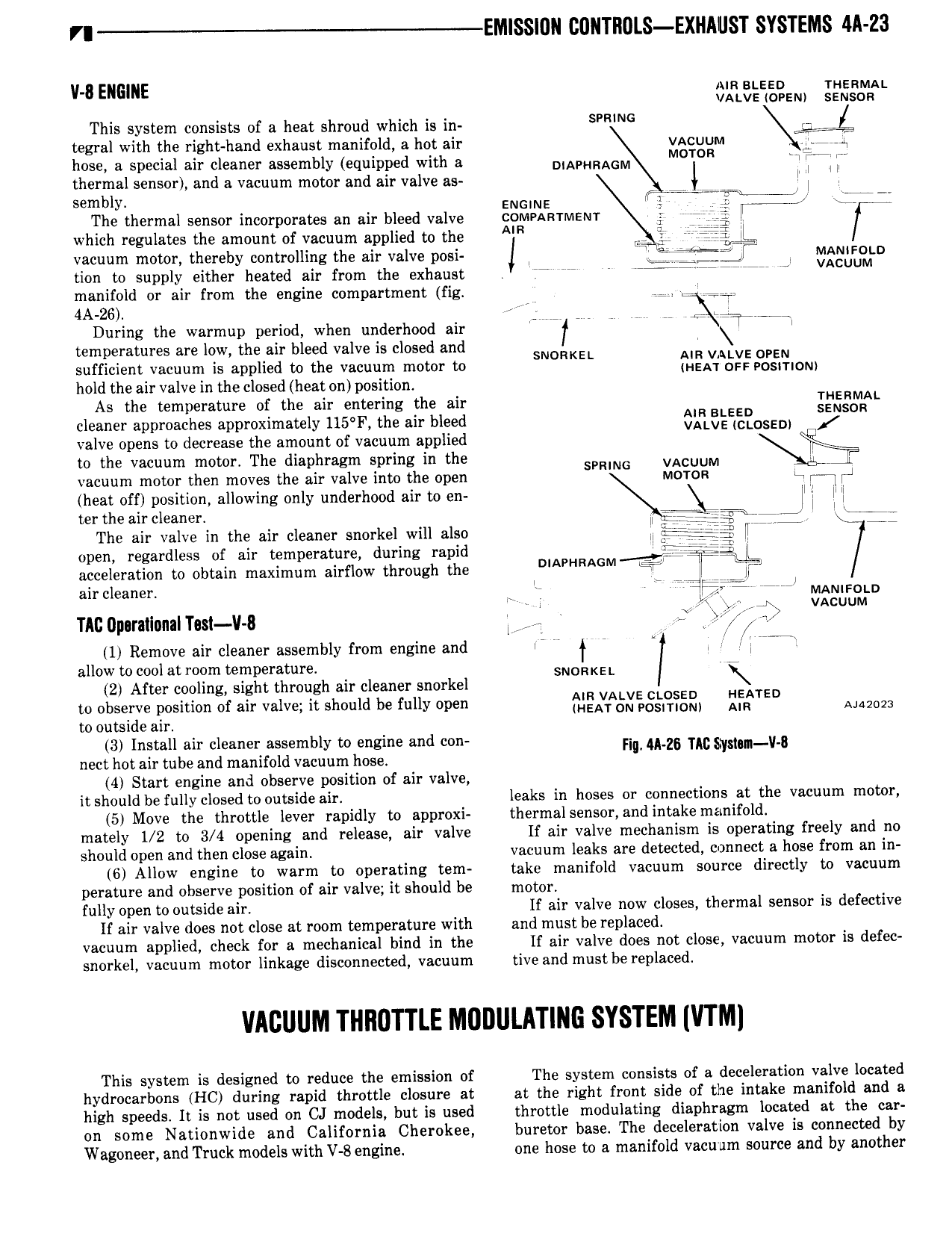
VI EM SS 0N CGNTHULS EXHAUST SYSTEMS 4A Z3 V U ENGINE am stszo msnwuu vatva cram ssmson This system consists of a heat shroud which is in R tegral with the right hand exhaust manifold a hot air vAcuuM d hose a special air cleaner assembly equipped with a DIAPHRAGM M T R T thermal sensor and a vacuum motor and air valve as l l l l sembly 1 r m W The thermal sensor incorporates an air bleed valve gg l llLERTMEN1 W 4 7 which regulates the amount of vacuum applied to the AIR E ii vacuum motor thereby controlling the air valve posi J fi T V MANIFOLU tion to supply either heated air from the exhaust ji W VACUUM manifold or air from the engine compartment fig 2 Z 4A 2o i During the warmup period when underhood air or W V V V 7 W E d7 rrr temperatures are low the air bleed valve is closed and SNDRKEL sufficient vacuum is applied to the vacuum motor to illaclild h Eigjdlglfiony hold the air valve in the closed heat on position As the temperature of the air entering the air ERMAL cleaner approaches approximately l15 F the air bleed cm i 0sED igson valve opens to decrease the amount of vacuum applied to the vacuum motor The diaphragm spring in the SPRING VACUUM vacuum motor then moves the air valve into the open Mcroe l heat off position allowing only underhood air to en r E ll l l ter the air cleaner 114Txf 7y X The air valve in the air cleaner snorkel will also ll riii 7 iw open regardless of air temperature during rapid i acceleration to obtain maximum airflow through the NAPHRAGM air cleaner J MANIFOLD i vAcuuM TAD Upuratlanalhst V 8 L4 3 1 Remove air cleaner assembly from engine and V T i I W allow to cool at room temperature SNORKEL Y 2 After cooling sight through air cleaner snorkel 2 ggsgirgeaplosition of air valve it should be fully open f l A xE 2 ig3 EFQTED AM2023 3 Install air cleaner assembly to engine and con Hq M z6 nc m v a nect hot air tube and manifold vacuum hose 4 Start engine and observe position of air valve it should be fully closed to outside air leaks in hoses or connections at the vacuum motor 5 Move the throttle lever rapidly to approxi thermal sensor and intake manifold mately 1 2 to 3 4 opening and release air valve lf air valve mechanism is operating freely and no should open and then close again vacuum leaks are detected connect a hose from an in 6 Allow engine to warm to operating tem take manifold vacuum source directly to vacuum perature and observe position of air valve it should be motor fully open to outside air If air valve now closes thermal sensor is defective If air valve does not close at room temperature with and must be replaced vacuum applied check for a mechanical bind in the lf air valve does not close vacuum motor is defec snorkel vacuum motor linkage disconnected vacuum tive and must be replaced VACUUM THIIUTTLE MUDULATING SYSTEM VTM This system is designed to reduce the emission of The system consists of a deceleration valve located hydrocarbons HC during rapid throttle closure at at the right front side of the intake manifold and a high speeds It is not used on CJ models but is used throttle modulating diaphragm located at the car on some Nationwide and California Cherokee buretor base The deceleration valve is connected by Wagoneer and Truck models with V 8 engine one hose to a manifold vacuum source and by another