Ford Parts Wiki | GM Parts Wiki
Home | Search | Browse
|
Technical Service Manual January 1975 |
|
Prev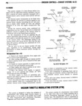
 Next
Next
4A 24 EMISSIDN G0l T 0LS EXHAlIST SYSTEMS VI hose to the throttle modulating diaphragm fig 3 Adjust by loosening the jamnut and turning 4A 27 the diaphragm assembly During high speed deceleration when manifold vacuum reaches approximately 21 to inches the THROTTLE MODULATING MANIFOLD deceleration valve triggers a vacuum signal to the DIAPHRAGM Q VACUUM throttle modulating diaphragm and causes a plunger E El VALVE gouge to move out and open the throttle slightly The in r creased throttle opening allows more air to enter the combustion chambers and lean out the overrich mix ture thereby reducing the emission of the hydrocar D s in I Ei bons 33 AX The deceleration valve calibration is preset at time Q of manufacture and normally does not require adjust ment To check and adjust the throttle modulating s diaphragm proceed as follows XJ 1 With engine not running and curb idle speed s previously set position throttle lever against curb idle 1 16 Ncu gpg CLEARANCE ad ustin screw NNE T sE T erutsirus nor nurmmcl J g THRDTTLE MODULATING 2 Measure clearance between the throttle DIAPHRAGM MM2 modulating diaphragm plunger and the throttle lever It should be 1 16 inch 0 062 inch Flu 4A 27 vacuum Thrnt1l Mndulsilng Sysnn Page Page llmrnl 4A 24 S ark Coolant Yun nrahira I1varrIil Swltch 4A 26 F P Solnnuld Cunlrul Swllch 4A 24 TCS Tas 4l Z4 Sulanuld Vacuum Valvs 4A 24 GENERAL automatic transmission or high gear manual trans mission the switch opens and breaks the ground cir The purpose of this system is to reduce the emis cuit to the solenoid vacuum valve sion of oxides of nitrogen by lowering the peak com At speeds under 32 to 36 mph automatic transmis bustion temperature during the power stroke The sys sion or lower gear ranges manual transmission the tem incorporates a solenoid vacuum valve a solenoid switch is closed and completes the ground circuit to control switch and related wiring and vacuum lines the solenoid vacuum valve fig 4A 28 and 44 29 This system is used only On manual transmissions the switch is operated by California CJ models the shifter shaft which is screwed into the transmis sion case SDl EIlUlI VACUUM VALVE On automatic transmissions the switch is located This valve is attached to the intake manifold at the gxxgh tp Oliiziggeger S n w h ag eY Iu 2 rear right side of the intake manifold V 8 engines or cable attaches to bothyends of the Switch At 32 0 36 0 P mksH si 9 0 me wks e ism mph 533 to 599 ans the switch will nm the cylinder engines When the valve is energized ground round Circuit circuit complete carburetor ported vacuum is blocked g and the distributor vacuum line is vented to atmos Tcs TEST phere through a port in the valve resulting in no vacuum advance When the valve is de energized A Vacuum gauge pmbytype est lamp and 8 jum sr s d u t P n2 p rt d vacuum is l d to the per wire are used to check the operation of the TCS distributor resulting in normal vacuum advance System 1 Turn ignition switch on in Disconnect wire from solenoid This switch opens or closes in relation to vehicle vacuum valve speed or gear range At speeds above 32 to 36 mph 3 Connect wire lead of test lzimptoground