Ford Parts Wiki | GM Parts Wiki
Home | Search | Browse
|
Technical Service Manual January 1975 |
|
Prev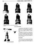
 Next
Next
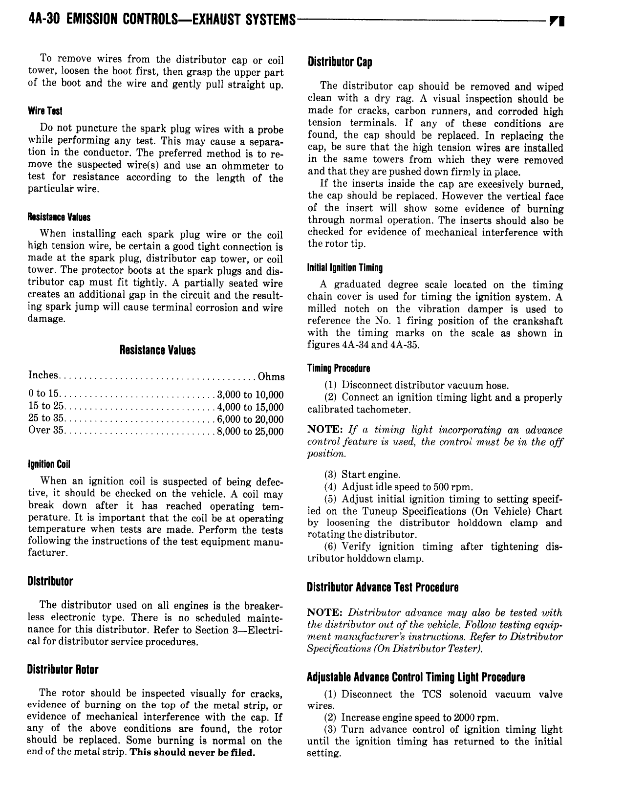
M 30 EMISSIUN 00llTl 0LS EXHAUST SYSTEMS T VI To remove wires from the distributor cap or coil lliglrlhulnr can tower loosen the boot first then grasp the upper part of the boot and the wire and gently pull straight up The distributor cap should be removed and wiped clean with a dry rag A visual inspection should be win ntl made for cracks carbon runners and corroded high tension terminals If an of these conditions are hilt notfpuncture the sparkhnlug wires with 8 i 0b found the can should beyreplaced In replacing the Y le per m g any ieee T le may cause sep cap be sure that the high tension wires are installed tion in the conductor The preferred method is to re in the same tnwsrs from which they were rsninved efth eueltecwd wird and ue ani hmhme er i and that they are pushed down firmly in place S or feels ence meme mg t t e een t e If the inserts inside the cap are excesively burned particular wml the cap should be replaced However the vertical face of the insert will show some evidence of burning lllilslllicl Villas through normal operation The inserts should also be when installing each spark nlug Wire nr the coil checked for evidence of mechanical interference with high tension wire be certain a good tight connection is the meme tm made at the spark plug distributor cap tower or coil tower The protector boots at the spark plugs and dis lem lumen nm tributor cap must fit tightly A partially seated wire A graduated degree scale located on the timing creates an additional gap in the circuit and the result chain cover is used for timing the ignition system A ing spark jump will cause terminal corrosion and wire milled notch on the vibration damper is used to damage reference the No 1 firing position of the crankshaft with the timing marks on the scale as shown in n asismmo Vanns figures 4A 34 and 4A 35 Tlnlnq Prnc dura Inches Ohms 1 Disconnect distributor Vacuum nose 0 to 15 l 3 000 to 10 000 2 Connect an ignition timing iight and a properly 15 to 25 l 4 000 to 15 000 calibrated tacndmttei 25 to 35 6 000 to 20 000 V ovenas s oootn2s ooo NOTE if Mira light ir r m m an advance control jealure is med the control must be in the off position Iqolilon Coil 4 When an ignition coil is suspectedlof beingtdefec itiiilgsirigllgineed to 500 rnrn me be wird the v 1 AM my in Adjust initial ignition timing to setting specif break d W after It has reached pe tmg tem ied on the Tuneup Specifications On Vehicle Chart perature It is important that the coil be at operating by lnnsening the distributor holddown chimp nnd temperature when tests are made Perform the tests rotating the distributor following the instructions of the test equipment manu 6 Verify ignition timing after tightening dis faemreri tributor holddown clamp m l llisirlhuior Advance Test Procedure Theidisiiiium Nihon ii i ig ig breaker NOTE nnnnnnn nn also be tested nn less e ectmiim Pye ere is no sc e u maint the distributor out of the vehicle Follow testing equip nance for this distribiitor Refer to Section 3 EIectri ment manufacturers imtmcmmsl Refer to Dirtrtlmtnr cal for distributor service procedures Spemftmtions On Distrtlmtm Tester m me r Miusiahla Advanca Donirol Timing Light Procudurs The rotor should be inspected visually for cracks 1 Disconnect the TCS solenoid vacuum valve evidence of burning on the top of the metal strip or wires evidence of mechanical interference with the cap If 2 Increase engine speedto2000 rpm any of the above conditions are found the rotor 3 Turn advance control of ignition timing light should be replaced Some burning is normal on the until the ignition timing has returned to the initial end of the metal strip This should never be tiled setting