Ford Parts Wiki | GM Parts Wiki
Home | Search | Browse
|
Technical Service Manual January 1975 |
|
Prev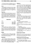
 Next
Next
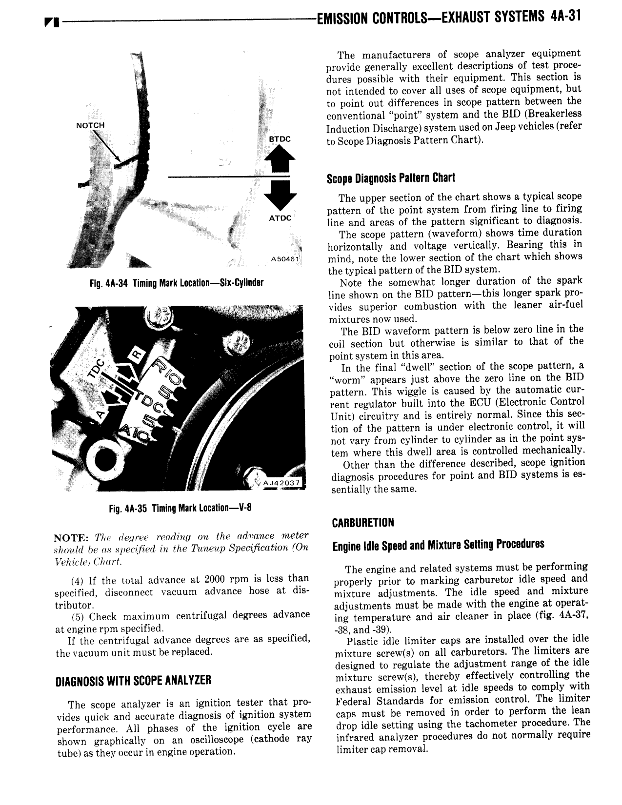
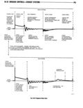
VI EM SS 0N COI TROLS EXIlAlIST SYSTEMS 4A 31 The manufacturers of scope analyzer equipment Y provide generally excellent descriptions of test proce i dures possible with their equipment This section is l not intended to cover all uses of scope equipment but 5 to point out differences in scope pattern between the NDTCH I conventional pomt system and the BID Breakerless I 3 lnduction Discharge system used on Jeep vehicles refer BTDC to Scope Diagnosis Pattern Chart V I T Scnpn Diagnosis Paiisrn Chart I T rag t m The upper section of the chart shows a typical scope v l ATDC pattern of the point system from firing line to firing T8 w line and areas of the pattern significant bo diagnosis I A The scope pattern waveform shows time duration i horigontally han voltage veri ca ly hBeari g hthi in I A5 46 min notet e ower section o t ec artw ic s ows the typical pattern of the BID system F ll 34 T I Mk I W lX DY d T Note the somewhat longer duration of the spark line shown on the BID pattern this longer spark pro 5 bag i V vides superior combustion with the leaner air fuel i V mixtures now used H The BID waveform pattern is below zero line in the V v coil section but otherwise is similar to that of the ag point system in this area 8 M In the final dwell section of the scope pattern a X r worm appears just above the zero line on the BID Q rf pattern This wiggle is caused gay the automagc cur Q rent regulator built into the E U E ectronic ontro Y Unit circuitry and is entirely normal Since this sec tion of the pattern is under electronic control it will V not vary from cylinder to cylinder as in the point sys x tem where this dwell area is controlled mechanically Other than the difference described scope ignition J IAMZOQ7 diagncasis procedures for point and BID systems is es sentia y the same Fig AA 35 Timing Mark Lmilnn V 8 CARNIIIETIUII NOTE The degree reading rm the advance meter slmulrl he as specified in me Thnzcup spectyimmm On Englnn liila Snead and Mlxiurn Sailing Prncuiiuras Vehicle Char Th ei 1 t d te t b rf if me wl dV M 2000 rpm is me 3 pmpe Zi SiZI Z Ziaifingyitrffriixf ldiepgpezimiii specified disconnect vacuum advance hose at dis mixture adjustmemsl The idle speed and mixture mbuwn adjustments must be made with the engine at operat 5 Check maximum cenmfugal degrees advance ing temperature and air cleaner in place fig 4A 37 at engine rpm specified 38 and 39 1 0 2 cenmfugal advance degrees are as 5p fl d Plastic idle limiter caps are installed over the idle the Vacuum mt must be replaced mixture screw s on all carburetors The limiters are designed to regulate the adjustment range of the idle DIAGNUSIS WITH SCOPE ANALYZER mixture screw s thereby effectively controlling the exhaust emission level at idle speeds to comply with The scope analyzer is an ignition tester that pro Federal Standards for emission control The limiter vides quick and accurate diagnosis of ignition system caps must be removed in order to perform the lean performance All phases of the ignition cycle are drop idle setting using the tachometer procedure The shown graphically on an oscilloscope cathode ray infrared analyzer procedures do not normally require tube as they occur in engine operation limiter cap removal