Ford Parts Wiki | GM Parts Wiki
Home | Search | Browse
|
Technical Service Manual January 1975 |
|
Prev

 Next
Next
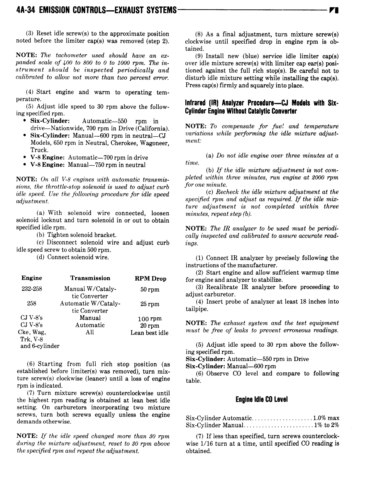
4A 34 EMISSIDN CDI TIl0LS EXIlAIIST SYSTEMS VI 3 Reset idle screw s to the approximate position 8 As a final adjustment turn mixture screw s noted before the limiter cap s was removed step 2 clockwise until specified drop in engine rpm is ob tained NOTE The tachometer used should have an ex 9 Install new blue service idle limiter cap s panded scale of 400 to 800 to 0 to 1000 rpm The in over idle mixture screw s with limiter cap ear s posi strument should be inspected periodically and tioned against the full rich stop s Be careful not to calibrated to allow not more than two percent error disturb idle mixture setting while installing the cap s Press cap s firmly and squarely inm place 4 Start engine and warm to operating tem yur I rmdur 6J 0 s wl x P mama unl nm m u l in Sl 5 Adjust idle speed to 30 rpm above the follow ing specified rpm CylInd r Engine Wlllioul Cmlyllc Convertor Six Cylinder Automstic 550 rpm in drive Nationwide 700 rpm in Drive California NOTE TO Ziiznpemaie fr iempemlmf Six Cylinder Manual 600 rpm in neutral CJ l s w p f m t 2 1 mw re WW Models 650 rpm in Neutral Cherokee Wagoneer mem Truck V 8 Engine Aul 0m8tlc 700 rpm ln drive l a Do not idle engine over three minutes at a V 8 Engine Manual 750 rpm in neutral e b If the idle mix Te udjwtmem is mt com u l NOTE On all V 8 engines with automatic transmis e Zf ethme i e mm mmm at 2000 mm sions the throttle stop solenoid is used to adjust curb idle speed Use the following procedure for idle speed ic Recheck th idle mwtulie adjiwtwwlit at the udjustmeml specified rpm and adjust as required lf the ldle mix ture adjustment is not completed within three a With solenoid wire connected loosen minutes repeatstep b solenoid locknut and turn solenoid in or out to obtain specified idle rpm NOTE The IR analyzer to be used must be periodi b Tighten solenoid bracket cally inspected and calibrated to assure accurate read c Disconnect solenoid wire and adjust curb ings idle speed screw to obtain 500 rpm d Connect solenoid wire 1 Connect IR analyzer by precisely following the instructions of the manufacturer 2 Start engine and allow sufficient warmup time E 8i T i i RPM DND for engine and analyzer to stabilize 232 258 Manual W Camly 50 rpm d 3 Regalibtrgate IR analyzer before proceeding to C be at jus car ure r 258 Aut at C mly 25 rpm 4 Insert probe of analyzer at least 18 inches into tic Converter tailpipa V M g V g Auglgxlc lgoorlgzin NOTE The exhaust system and the test equipment Ckey Wagy All Lean bestidle must be free of leaks to prevent erroneous readings Trk V 8 d 6 l ll 5 Adjust idle speed to 30 rpm above the follow an cy In er ing specified rpm Six Cylinder Automatic 550 rpm in Drive 6 Starting from full rich stop position as Six Cvll d M mual l 00 rpm established before limiter s was removed turn mix 6 Observe C0 level and compare to allowing ture screw s clockwise leaner until a loss of engine l 8l l rpm is indicated 7 Turn mixture screw s counterclockwise until the highest rpm reading is obtained at lean best idle EW MI cu I O setting On carburetors incorporating two mixture gmwsl ml bah wm y the Mi sl Cyt d Automatic 1 0 mt email S t Erm Six Cylinder Manual 1 to 2 NOTE H the idle speed changed more than 80 rpm 7 If less than specified turn screws counterclock during the mixture adjustment reset to 30 rpm above wise 1 16 turn at a time until specified CO reading is the specified rpm and repeat the adjustment obtained

 Next
Next