Ford Parts Wiki | GM Parts Wiki
Home | Search | Browse | Marketplace | Messages | FAQ | Guest
|
Technical Service Manual January 1975 |
|
Prev

 Next
Next
353353
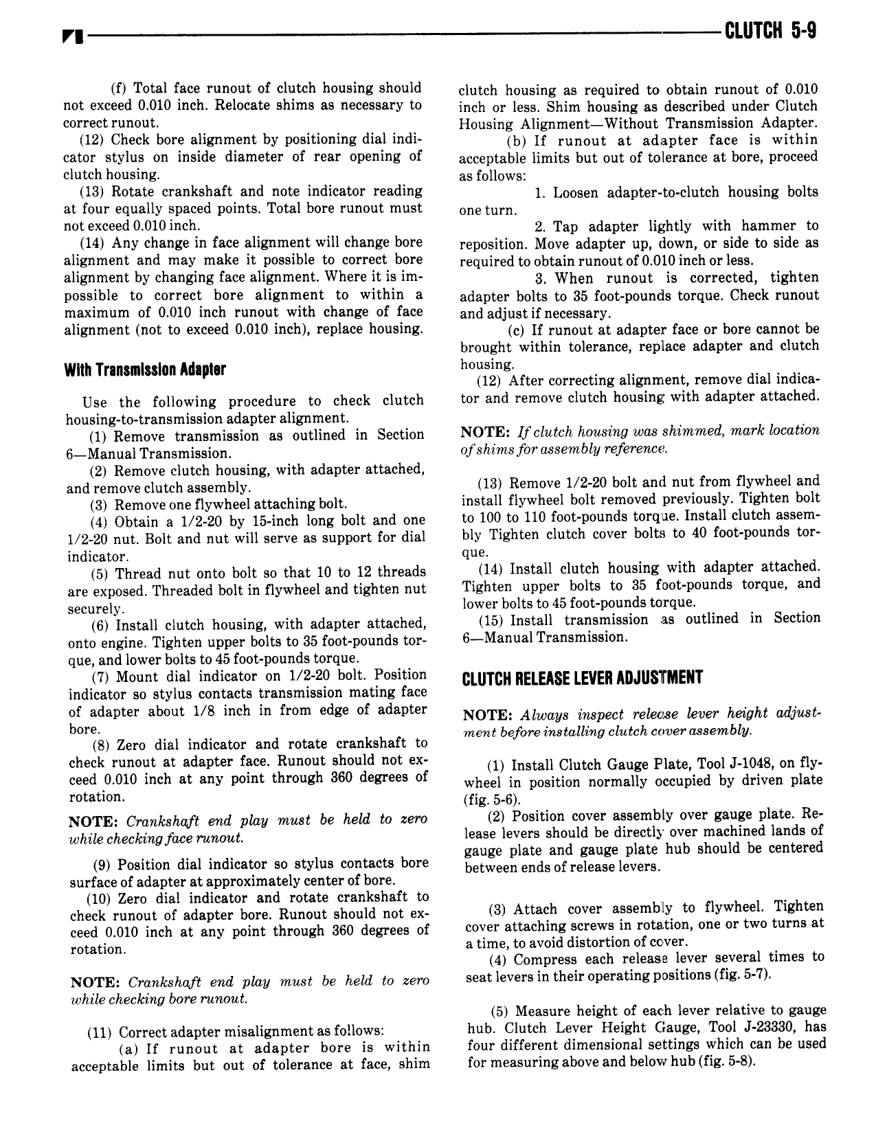
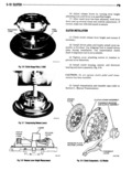
VI CLUTCH 5 9 if Total face runent ef clutch hensina sheuld clutch housing as required to obtain runout of 0010 mt Exceed 0010 inch R l e ennne es necessary in inch or less Shim housing as described under Clutch e Housing Alignment Without Transmission Adapter 12 Check bore alignment by positioning dial indi b I nonont nt nonntet nee ie Within eater SU lun en lnelde diameter nf Yee cpeninz ef acceptable limits but out of tolerance at bore proceed clutch housing as follows 13 Rotate crankshaft and note indicator reading Loosen aoontet to olntth housing bolts at four equally spaced points Total bore runout must one turn d0 010i ch 2 Tap adapter lightly with hammer to 14 Any change in face alignment will chanse here reposition Move adapter up down or side to side as alignment and may make it possible to cerrect here required to obtain runout or 0 010 inch oi less alignment by changing face alignment Where it is im 3 when runout is connected tighten D lbl t 0l l t befe ellgnment te within 3 adapter bolts to 35 foot pounds torque Check runout maximum of 0 010 inch runout with change of face and adjustif necessary alignment not to exceed 0 010 inch replace housing o If runout at adopter soo or bono cannot be brought within tolerance replace adapter and clutch Wlln Transmission Maplor housing 12 After correcting alignment remove dial indica Use the following procedure to check clutch tor and remove clutch housing with adapter attached housing to transmission adapter alignment 1 Remove transmission as outlined in Section NOTE U clutch housing was shimmed mark location 6 Manual Transmission of shims for assembly reference 2 Remove clutch housing with adapter attached and remove clutch gssembly 13 Remove 1 2 20 bolt and nut from flywheel and 3 Remove one flywheel attaching bolt install flywheel bolt removed previously Tighten bolt 4 Obtain a 1 2120 by 15 inoh long bolt and one to 100 to 110 foot pounds torque Install clutch assem 1 2 20 nut Bolt and nut will serve as support for dial bly Tighten clutch cover bolts to 40 foot p0unds tor indicator que 5 Thread nut onto bolt so that 10 to 12 threads 14 Install clutch housing with adapter attached are exposed Threaded bolt in nywheel and tighten nut Tighten upper bolts to 35 fvct pounds torque and securely lower bolts to 45 foot pounds torque 6 install clutch housing with adapter attached 15 Install transmission as outlined in Section onto engine Tighten upper bolts to 35 foot pounds tor 6 Manual Transmission que and lower bolts to 45 foot pounds torque 7 Mount dial indicator on 1 2 20 bolt 1 osition cw c RELEASE LEVER ADJUSTMENT indicator so stylus contacts transmission mating face ojiridapter about 1 8 inch in from edge of adapter NOTE Always inspect Telewe kw height mnmn 8 Zero dial indicator and rotate crankshaft to mem befwe msmllmg clutch wvgrusembn check runout at adapter face Runout should not ex 1 tuscan Clutch Gauge Plate Tool L1048 on ny need 0010 lncn at any point tnmngn 360 degrees ef wheel in position normally occupied by driven plate rotation fig 5 6 4 NOTE Crankshaft and play must be held to zero 2 Position cover assembly over gauge plate Re whilo phgpk ingf 7 g9ru7tg14 f lease levers should be directly over machined lands of to i i 0 ni indicator stylus 0 c bore 5 5 3 353353 hub shore be Mme surface of adapter at approximately center of bore 10 Zero dial indicator and rotate crankshaft to check runout of adapter bore Runout should not ex 3 Attach cover assembly to flywheel Tighten good O 0 0 inch at any point through 360 degrees of cover attaching screws in rotation one or two turns at rotation a time to avoid distortion of cover 4 Compress each release lever several times to NOTE Crankshaft end play must be held to zero seat levers in their operating positions fig 5 7 while checking bore runout 5 Measure height of each lever relative to gauge 11 Correct adapter misalignment as follows hub Clutch Lever Height Gauge Tool J 23330 has a If runout at adapter bore is within four different dimensional settings which can be used acceptable limits but out of tolerance at face shim for measuring above and below hub fig 5 8

 Next
Next