Ford Parts Wiki | GM Parts Wiki
Home | Search | Browse | Marketplace | Messages | FAQ | Guest
|
Technical Service Manual January 1975 |
|
Prev

 Next
Next
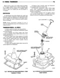
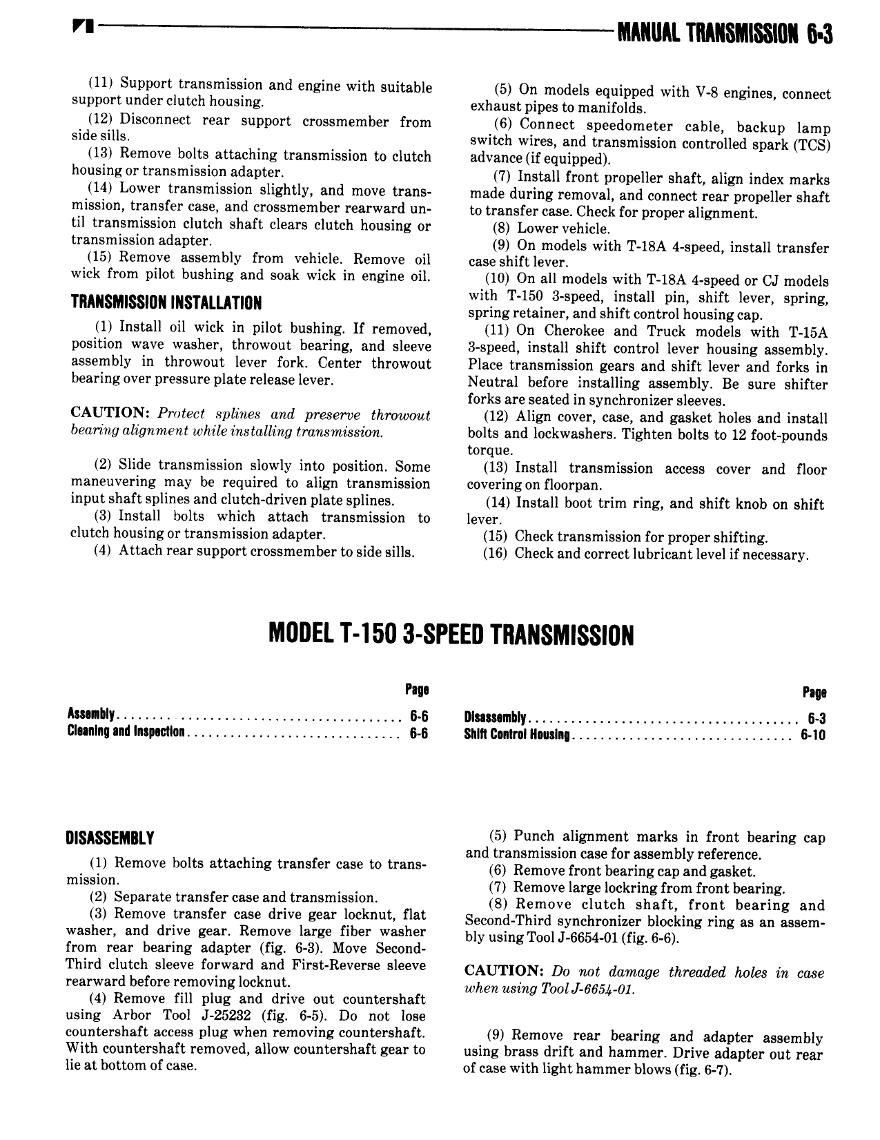
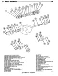
VI IIIAIIIIAL IIIIIIMIISSION 6 3 11 Support transmission and engine with suitable 5 On models equipped with V 8 engines connect support under clutch housing exhaust pipes to manifolds 12 Disconnect rear support crossmember from 6 Connect speedometer cable backup lamp side sills switch wires and transmission controlled spark TCS 13 Remove bolts attaching transmission to clutch advance if equipped housing or transmission adapter 7 Install front propeller shaft align index marks 14 Lower transmission slightly and move trans made during removal and connect rear propeller shaft mission transfer case and crossmember rearward un to transfer case Check for proper alignment til transmission clutch shaft clears clutch housing or 8 Lower vehicle transmission adapter 9 On models with T 18A 4 speed install transfer 15 Remove assembly from vehicle Remove oil case shift lever wick from pilot bushing and soak wick in engine oil 10 On all models with T 18A 4 speed or CJ models with T 150 3 speed install pin shift lever spring Tmnsmlsslun ISTMMTIDN spring retainer and shift control housing cap 1 Install oil wick in pilot bushing If removed 11 On Cherokee and Truck models with T 15A position wave washer throwout bearing and sleeve 3 speed install shift control lever housing assembly assembly in throwout lever fork Center throwout Place transmission gears and shift lever and forks in bearing over pressure plate release lever Neutral before installing assembly Be sure shifter forks are seated in synchroniper sleeves CAUTION Protect splines and preserve throwout 12 Align cover case and gasket holes and install bearing alignment while installing transmission bolts and lockwashers Tighten bolts to 12 foot pounds torque 2 Slide transmission slowly into position Some 13 Install transmission access cover and floor maneuvering may be required to align transmission oovering on floorpan input shaft splines and cIutch driven plate splines 14 Install boot trim ring and shift knob on shift 3 Install bolts which attach transmission to lever clutch housing or transmission adapter 15 Check transmission for proper shifting 4 Attach rear support crossmember to side sills 16 Check and correct lubricant level if necessary MODEL T I5O 3 SPEED TRANSMISSION Pm Fm Amnlly G 6 Illmumhty M Dlunlnn nil Inmctlan M Slim Ilnnlnl Nnuslnq 6 I0 DISASSEMILY 5 Punchaligument marks in front bearing cap and transmission case for assembly reference 1 Remove bolts attaching transfer case to trans 6 Remnve from bearing cap and gaskmn mlsslml 7 Remove large lockring from front bearing 2 Separate transfercase and transmission 8 Remove clutch Shan from bearing and 3 R m v transfer cas drwe gear l cl m t nat Second Third synchronizer blocking ring as an assem washer and drive gear Remove large fiber washer my using TOO J 6654 m fig 6 6 from rear bearing adapter fig 6 3 Move Second Third clutch sleeve forward and First Reverse sleeve CAUTION D0 not damage threaded hglee in edge rearward before removing locknut when nsina TOO 66 01 4 Remove fill plug and drive out countershaft using Arbor Tool J 25232 fig 6 5 Do not lose countershaft access plug when removing countershaft 9 Remove rear bearing and adapter assembly With countershaft removed allow countershaft gear to using brass drift and hammer Drive adapter out rear lie at bottom of case of case with light hammer blows fig 6 7

 Next
Next