Ford Parts Wiki | GM Parts Wiki
Home | Search | Browse
|
Technical Service Manual January 1975 |
|
Prev

 Next
Next
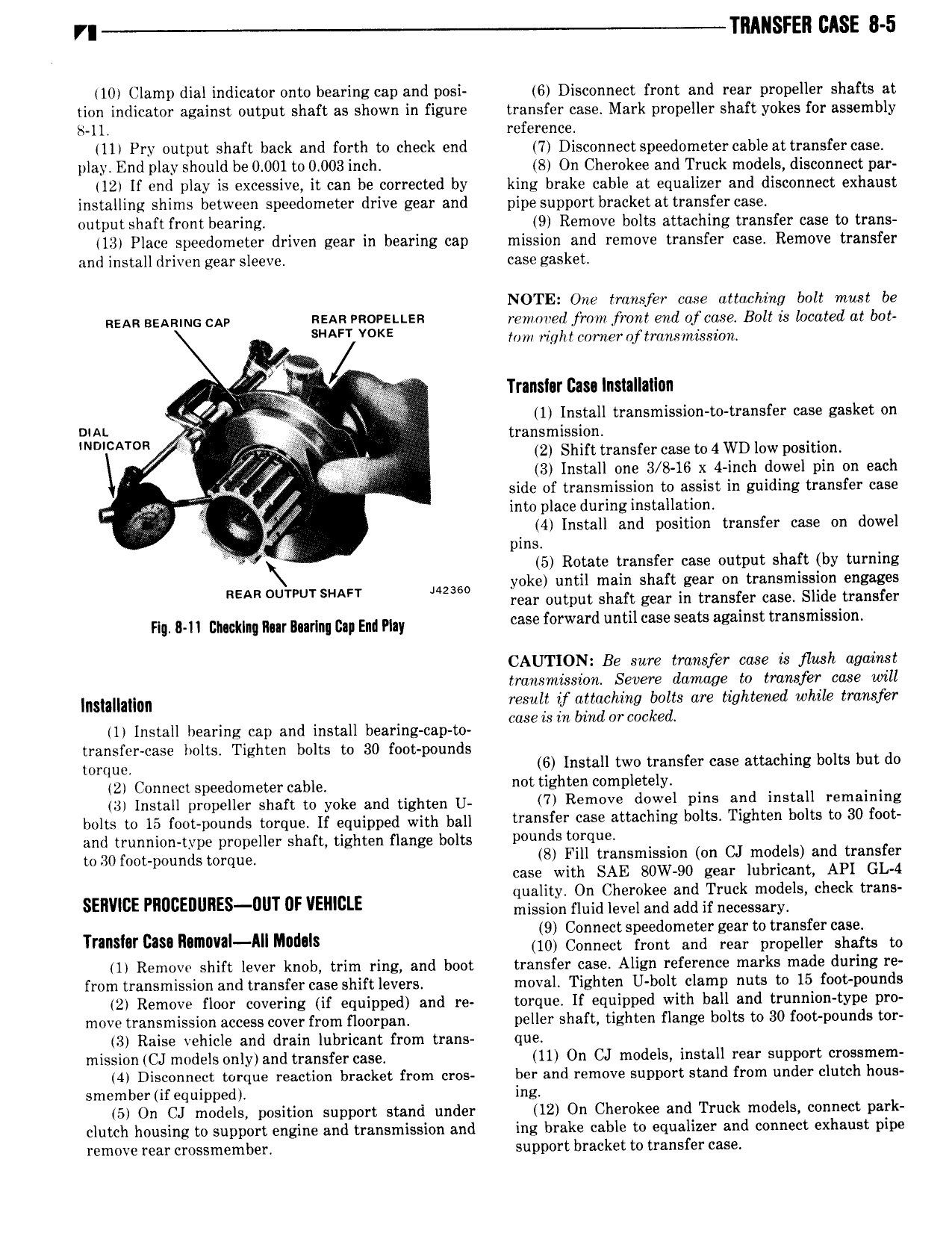
VI TIIAI SFEII BASE 8 5 10 Clamp dial indicator onto bearing cap and posi 6 Disconnect front and rear propeller shafts at tion indicator against output shaft as shown in figure transfer case Mark propeller shaft yokes for assembly S 11 reference ll Pry output shaft back and forth to check end 7 Disconnect speedometer cable at transfer case play End play should be 0 001 to 0 003 inch 8 On Cherokee and Truck models disconnect par 12 lf end play is excessive it can be corrected by king brake cable at equalizer and disconnect exhaust installing shims between speedometer drive gear and pipe support bracket at transfer case output shaft front bearing 9 Remove bolts attaching transfer case to trans 13 Place speedometer driven gear in bearing cap mission and remove transfer case Remove transfer and install driven gear sleeve case gasket NOTE One transfer case attaching bolt must be REAR BEARING CAR REAR rsorettsn renmrerl jrmn front end ofcase Bolt is located at b0t S V KE Ion right corner oftransimission I r it Translur Casa Inslallailnn ix E 1 Install transmission no transfer case gasket on my CATOR transmission rf i 4 2 Shift transfer case to 4 WD low position 3 Install one 3 8 16 x 4 inch dowel pin on each side of transmission to assist in guiding transfer case into place during installation Qovi 4 Install and position transfer case on dowel ff 4 pins O 5 Rotate transfer case output shaft by turning yoke until main shaft gear on transmission engages REAR OUTPUT SHAFT NNW rear output shaft gear in transfer case Slide transfer HW 8 chlmw mr umm an EM my case forward until case seats against transmission CAUTION Be sure transfer cose is flush against transmission Severe damage to transfer case will m mm result if attaching bolts are tightened while transfer 1 Install hearing cap and install bearing cap to m 1smhL7 d0TCOCked transfer case lvolts Tighten bolts to 30 foot pounds wmul 6 Install two transfer case attaching bolts but do 2 Connect speedometer cable not tighten 0mPl t lY 4 mszau pmpenier shaft to yoke and tighten U 7 Remove dowel pins and install remaining bolts to 15 f0 p0RRdS tmqug H equipped with bal transfer case attaching bolts Tighten bolts to 30 foot and trunnion type propeller shaft tighten flange bolts Pimnds t Q 0 30 mppounds mrqug S Fill transmission on CJ models and transfer case with SAE BOW 90 gear lubricant API GL 4 quality On Cherokee and Truck models check trans SERVWE PImcEnunES uT 0F VEHICLE mission fluid level and add if necessary 9 Connect speedometer gear to transfer case Tnnshr cas n m MlM d I 10 Connect front and rear propeller shafts to 1 Remove shift lever knob trim ring and boot transfer case Align reference marks made during re from transmission and transfer case shift levers moval Tighten U bolt clamp nuts to 15 foot pounds 2 Remove floor covering if equipped and re torque If equipped with ball and trunnion type pro movc transmission access cover from floorpan peller shaft tighten flange bolts to 30 foot pounds tor 3 Raise vehicle and drain lubricant from trans que mission CJ models only and transfer case 11 On CJ models install rear support crossmem 4 Disconnect torque reaction bracket from cros ber and remove support stand from under clutch hous smember if equipped ing 5 On CJ models position support stand under 12 On Cherokee and Truck models connect park clutch housing to support engine and transmission and ing brake cable to equalizer and connect exhaust pipe remove rear crossmember support bracket to transfer case

 Next
Next