Ford Parts Wiki | GM Parts Wiki
Home | Search | Browse
|
Technical Service Manual January 1975 |
|
Prev

 Next
Next
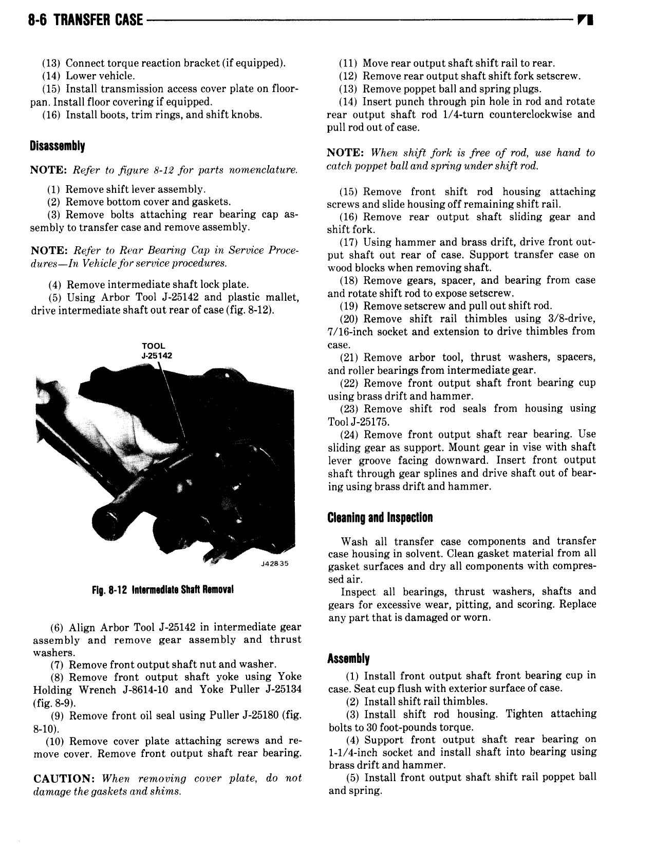
8 6 TRANSFER CASE n 13 Connect torque reaction bracket if equipped 11 Move rear output shaft shift rail to rear 14 Lower vehicle 12 Remove rear output shaft shift fork setscrew 15 Install transmission access cover plate on floor 13 Remove poppet ball and spring plugs pan Install floor covering if equipped 14 Insert punch through pin hole in rod and rotate 16 Installboots trim rings and shift knobs rear output shaft rod 1 4 turn ccunterclockwise and pull rod out of case Dlnsumblr NOTE When shift jbrk is free of rod use hand to NOTE Refer to figure 8 12 for parts nomenclature earch polmet oollmtrt SP U de Slt ftrod U Remove Shiftlevef S mblY 15 Remove front shift rod housing attaching 2 Remove bottom cover and zaskets screws and slide housing off remaining shift rail 3 Remove bolts otteellmg rear oearmg eel es 16 Remove rear output shaft sliding gear and sembly to transfer case and remove assembly shift fork 1 N TE Refer 0 RW Beam Cap in Sem Pm pol llali Z th i Zl IZ lel S iZ lKl gllieirizlgiii dures 1n Vehiclejbr service procedures Wood blocks when remgving shaft 4 Remove intermediate shaft lock plate 18 Remove geore soeoeth and bearing from cose 5 Using Arbor Tool J 25142 and plastic mallet and rotate Shlrtrodtoexooso Seteerevv drive intermediate shaft out rear of case fig 8 12 19 R0m0V S F W and pull out Shift rod 20 Remove shift rail thimbles using 3 8 drive 7 16 inch socket and extension to drive thimbles from wor case 25 2 21 Remove arbor tool thrust washers spacers and roller bearings from intermediate gear 22 Remove front output shaft front bearing cup using brass drift and hammer 23 Remove shift rod seals from housing using Tool 25175 24 Remove front output shaft rear bearing Use I V V sliding gear as support Mount gear in vise with shaft lever groove facing downward Insert front output shaft through gear splines and drive shaft out of bear 4 in ing using brass drift and hammer lilunlnq and Inspwtlan Wash all transfer case components and transfer I case housing in solvent Clean gasket material from all 2 5 gasket surfaces and dry all components with compres sed air rll o l2 llllelvnelllrte Sven nmevrl Inspect all bearings thrust wasihers shafkts pnd gears or excessive wear pitting an scoring ep ace any part that is damaged or worn 6 Alngn Arbor Tool J 25142 in intermediate gear assembly and remove gear assembly and thrust washers 7 Remove front output shaft nut and washer Assullllv B Remove front output shaft yoke using Yoke 1 Install front output shaft front bearing cup in Holding Wrench J 8614 10 and Yoke Puller J 25134 case Seatcup flush with exteriorsurfaceofcase fig 8 9 2 Install shift rail thimbles 9 Remove front oil seal using Puller J 25180 fig 3 Install shift rod housing Tighten attaching 8 10 bolts to 30 foot pounds torque 10 Remove cover plate attaching screws and re 4 Support front output shaft rear bearing on move cover Remove front output shaft rear bearing 1 1 4 inch socket and install shaft into bearing using brass drift and hammer CAUTION When removing cover plate do not 5 Install front output shaft shift rail puppet ball damage the gaskets and shims and spring

 Next
Next