Ford Parts Wiki | GM Parts Wiki
Home | Search | Browse
|
Technical Service Manual January 1975 |
|
Prev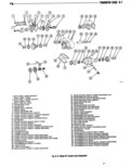
 Next
Next
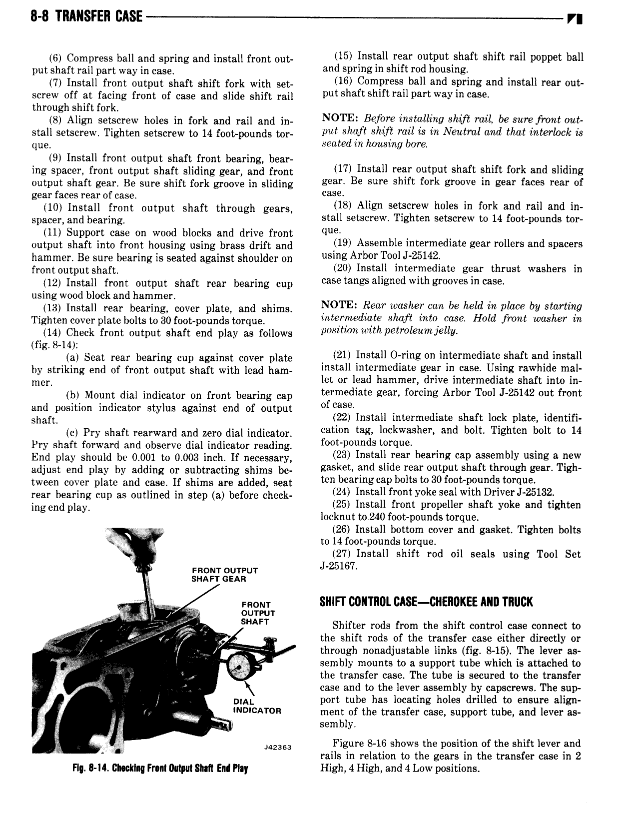
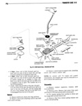
8 8 TRANSFER EASE r 6 Compress ball and spring and install front out lo lllsrall rear olltPlll Sllafl Shift rail wvvct llall put shaft rail part way in case and 5PrlllE lrl l1I F d lI0 1 I B 7 Install front output shaft shift fork with set 16 C mPl sS bell and SPI and l ll roar our screw off at facing front of case and slide shift rail pm Sllaftsllllt l allPortWaYlll mso through shift fork 8 Align setscrew holes in fork and rail and in NOTE Before inololllflg Shift mil be u f 0 I Wi stall setscrew Tighten setscrew to 14 foot pounds tor lm Shoji Shift ro is W Neulml md that i l0 k 73 que seated m housing bore 9 Install front output shaft front bearing bear ing spacer mnt putput shatt sliding geaiu and mnt 17 Install rear output shaft shift fork and sliding output shaft gear Be sure shift fork groove in sliding lioolo Bo Sure slllfr fork groove in Kerr faces I I of gear faces rear of case caros lg install mnt output sha t tlimugli genre 18 Align setscrew holes in fork and rail and in spaeen and bearing stall setscrew Tighten setscrew to 14 foot pounds tor 11 Support case on wood blocks and drive front q Output shu t inte mnt housing using brass drift and 19 Assemble intermediate gear rollers and spacers hammer Be sure bearing is seated against shoulder on llslllg Arbor T l 25142 mnt uutput sha t 20 Install intermediate gear thrust washers in 12 Install front output shaft rear bearing cup Case tongs ollgrlod Wltll Zroovosln wso using wood block and hammer 4 13 Install rear bearing cover plate and shims NOTE Rear heT um be hold m Place bl Slartlng Tighten eduei plate bolts td 30 i u0t ndunds torque mtermedzate shaft mto case Hold from washer in 14 Check front output shaft end play as follows posmollw th7 g ole 7olll fig 8 14 ia seat i ear bearing eun against eevei plate 21 Install O ring on intermediate shaft and install by striking end df mnt Output shaft with lead ham install intermediate gear in case Using rawhide mal nnen let or lead hammer drive intermediate shaft into in ibl Mount dial indicator on mnt bearing can termediate gear forcing Arbor Tool J 25142 out front and position indicator stylus against end of output f sha t 22 Install intermediate shaft lock plate identifi ie pry shaft rearward and new dial indieuton cation tag lockwasher and bolt Tighten bolt to 14 Pry shaft forward and observe dial indicator reading l o t I o ds tol q End pisy should be 0 001 to 0 003 msi If sscesssw 3 I Il r I s can Msemblv z ww adjust end play by adding Oi subtracting shims be gasket and slide rear output shaft through gear Tigh tween cover plate and case If shims are added seat ben beam cap bolts to 30 looblloulldo torollo rear bearing cup as outlined in step a before check 24 I Ilfr t Yoko Seal wlth Drlvor 25132 ineend play 25 Install front propeller shaft yoke and tighten locknut to 240 foot pounds torque 26 Install bottom cover and gasket Tighten bolts R tl to 14 foot pounds torque 27 Install shift rod oil seals using Tool Set snout cuveur J 25l67 l suAr r cnn l l mom SIIIFT 00l TR0l CASE 2l EROKEE AIIII TRUCK it li oureur TY g Sl AFT Shifter rods from the shift control case connect to r ff i V e the shift rods of the transfer case either directly or through nonadjustable links fig 8 15 The lever as m sembly mounts to a support tube which is attached to h the transfer case The tube is secured to the transfer is case and to the lever assembly by capscrews The sup V plat port tube has locating holes drilled to ensure align i J INDICATOR ment of the transfer case support tube and lever as K sembly Mess Figure 8 16 shows the position of the shift lever and rails in relation to the gears in the transfer case in 2 F I II Glncklnq Front llnlput Stall End Play High 4 High and 4 Low positions