Ford Parts Wiki | GM Parts Wiki
Home | Search | Browse
|
Technical Service Manual January 1975 |
|
Prev
 Next
Next
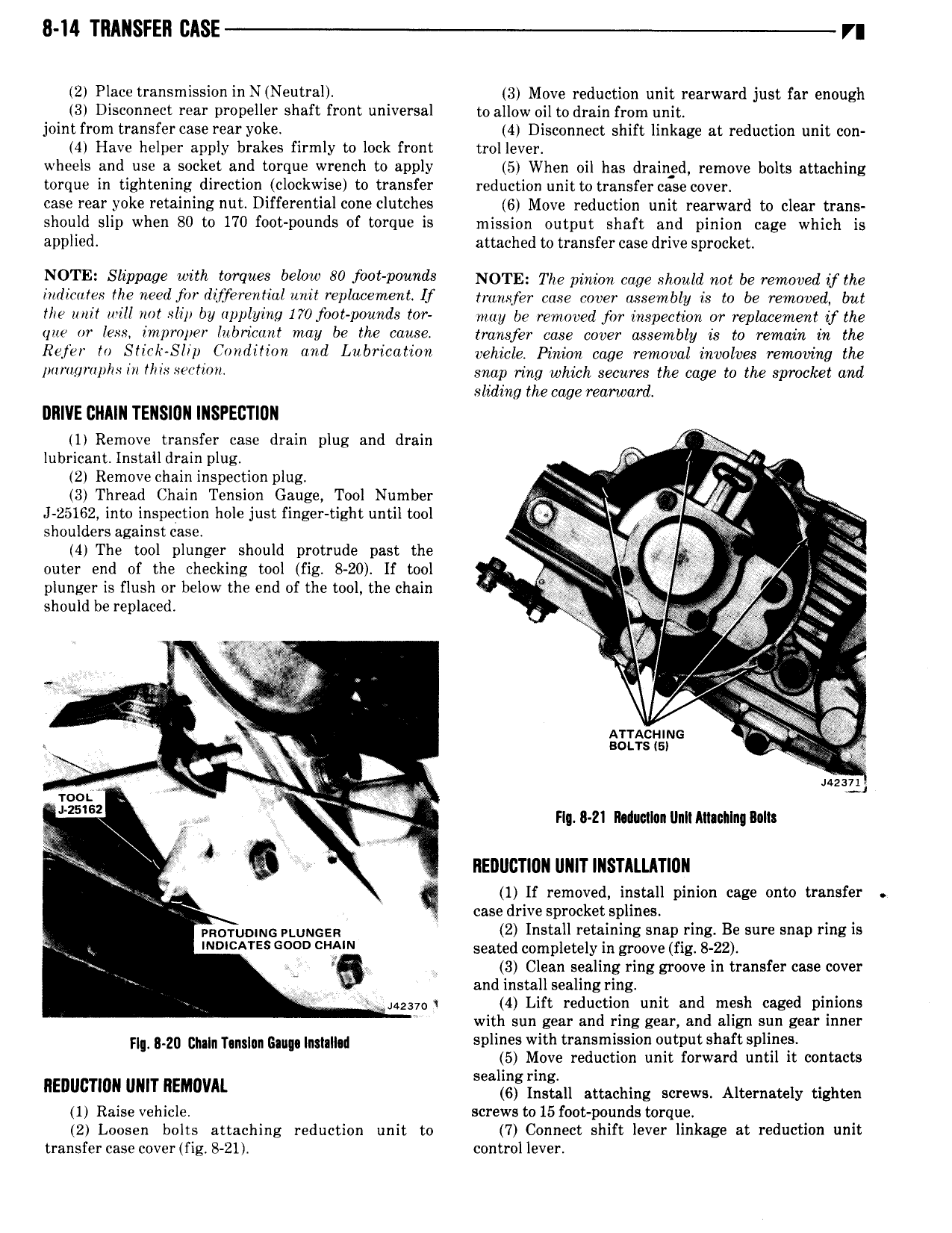
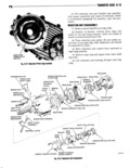
8 I4 TRANSFER CASE V 2 Place transmission in N Neutral 3 Move reduction unit rearward just far enough 3 Disconnect rear propeller shaft front universal to allow oil to drain from unit joint from transfer case rear yoke 4 Disconnect shift linkage at reduction unit con 4 Have helper apply brakes firmly to lock front trol lever wheels and use a socket and torque wrench to apply 5 When oil has drained remove bolts attaching torque in tightening direction clockwise to transfer reduction unit to transfer case cover case rear yoke retaining nut Differential cone clutches 6 Move reduction unit rearward to clear trans should slip when 80 to 170 foot pounds of torque is mission output shaft and pinion cage which is applied attached to transfer case drive sprocket N0 l E Sliiwuae with wrques below 80 fvvf rounds NOTE The pinion cage should me be removed y the indicates the neerljirr dirferenlial unit replacement If mmsfev vase cover mgsembgy is gv be removed yu the unit will not slip by applying 170 foot pounds tar may be removed for inspection ar replacement if the que or less improper lulzricant may be the cause transfer case cover assembly is to remain in the Rejer to Stir r Slip Corulilimz and Lubrication vehicle Pimvv vqge removal involves removing the l fV Hl l h lll this fl snap ring which secures the cage to the sprocket and sliding the cage rearward DRIVE CNIIN TENSIUN INSPECTION 1 Remove transfer case drain plug and drain lubricant insiau amen plug J5 M gw 2 Remove chain inspection plug l l 3 Thread Chain Tension Gauge Tool Number y v yr J 25162 into inspection hole just finger tight until tool Q Xl i shoulders against case l ll x 4 The tool plunger should protrude past the Q i ttl outer end of the checking tool fig 8 20 If tool F 4 ls 4 a plunger is flush or below the end of the tool the chain E sg should be replaced gg aff l J vi aw 1 v in g a j ss i Arracuiuc wb V sous ts 1 V mi sum roo i s wz J n zi mmmnuiinnmennnjmnn zi ff s G NEDIICTIDN I INITINSTIlI NTION 1 If removed install pinion cage onto transfer f case drive sprocket splines PRDTUDWG PLUNGER 2 Install retaining snap ring Be sure snap ring is V INWCATES GOOD A N seated completely in groove fig 8 22 Q 3 Clean sealing ring groove in transfer case cover V and install sealing ring js2 7 t 4 Lift reduction unit and mesh caged pinions with sun gear and ring gear and align sun gear inner Fm g gg gm n mu MMM splines with transmission output shaft splines 5 Move reduction unit forward until it contacts sealin rin IIEnI IcTIn UNIT REMIWAL li lnsiall attaching screws Alternately tighten 1 Raise vehicle screws to 15 foot pounds torque 2 Loosen bolts attaching reduction unit to 7 Connect shift lever linkage at reduction unit transfer case cover fig 8 21 control lever