Ford Parts Wiki | GM Parts Wiki
Home | Search | Browse
|
Technical Service Manual January 1975 |
|
Prev
 Next
Next
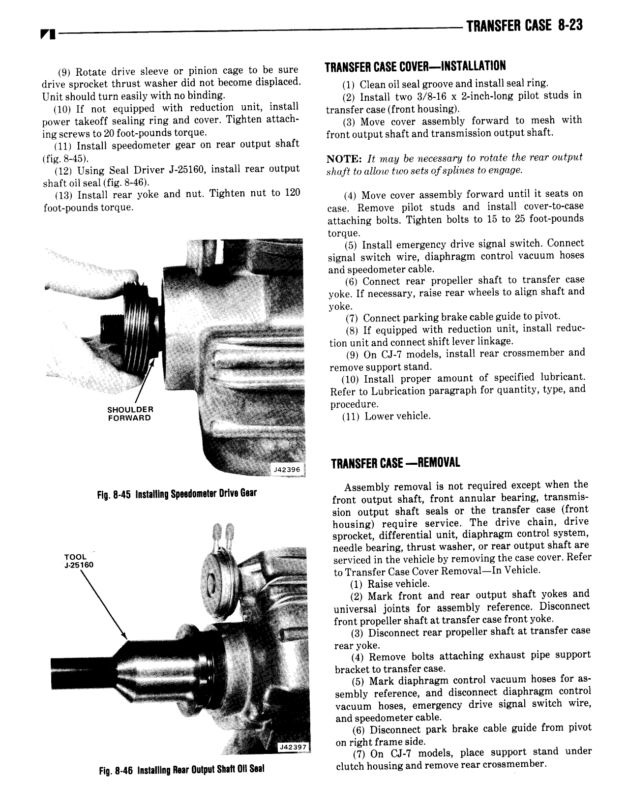
r TRANSFER CASE 8 23 9 Rotate drive sleeve or pinion cage to be sure TRANSFER CASE BUYER IRSTRLLRTIUR drive sprocket thrust washer did not become displaced 1 Clean Dil Sealgmove and install Seal ring U h ld muy h 0 bi 2 instaii two 3 8 is X z a o1q 1o g pilot studs in 10 lf not equipped with reduction unit install transfercas fmmh0 sing power takeoff sealing ring and cover Tighten attach 3 Move cover assembly forward to mesh with mg Screws 20 f p u dS t qu front output shaft and transmission output shaft 11 Install speedometer gear on rear output shaft fig 8 45 NOTE It may be necessary to rotate the rear output Sh LiFss F f Esxlver I 25160 install rear Output shaft to allow two sets of splines to engage 13 Install mar y k and mm Tighten nut m 120 4 Move cover assembly forward until it seats on foot pounds torque mso Remove pilot studs and install cover to case attaching bolts Tighten bolts to 15 to 25 foot pounds torque V 5 Install emergency drive signal switch Connect L signal switch wire diaphragm control vacuum hoses eg and speedometercable o 4 ii 6 Connect rear propeller shaft to transfer case i Uixiyin yoke If necessary raise rear wheels to align shaft and i sy 5 q N yoke q ii 7 Connect parking brake cable guide to pivot 2 if Z S If equipped with reduction unit install reduc T J i t I tion unitandconnectshiftleverlinkage Q iq 9 On CJ 7 models install rear crossmember and 1 i Q remove support stand V A E r 10 Install proper amount of specified lubricant V V Refer to Lubrication paragraph for quantity type and suoutosa V At g A procedure FORWARD QR T V 11 Lower vehicle n a 4 3 TRANSFER CASE REIAUVAI Hm 845 Imlum swdumm um uw Assembly removal is not required except when the front output shaft front annular bearing transmis sion output shaft seals or the transfer case front g gi housing require service The drive chain drive sprocket differential unit diaphragm control system TOOL l W needle bearing thrust washer or rear output shaft are I 25160 paw serviced in the vehicle by removing the case cover Refer its to Transfer Case Cover Removal In Vehicle 5 1 Raise vehicle gig je U 2 Mark front and rear output shaft yokes and Qi universal joints for assembly reference Disconnect Y 29 front propeller shaft at transfer case front yoke r V at 3 Disconnect rear propeller shaft at transfer case R e rear yoke 4 Remove bolts attaching exhaust pipe support bracket to transfer case C 5 Mark diaphragm control vacuum hoses for as sembly reference and disconnect diaphragm control ii vacuum hoses emergency drive signal switch wire and speedometercable 1 6 Disconnect park brake cable guide from pivot on right frame side 7 On CJ 7 models place support stand under Flg IME Inslalllnq Roar Ilulpli S1IIl l 0Il Sill clutch housing and remove rear crossmember